
A Review of the Use of Electrolytic Cells for Energy and Environmental Applications
by
 , and
, and
Ana P. R. A. Ferreira
1, 
Raisa C. P. Oliveira
1,2 ,
,
Maria Margarida Mateus
2,3 and
Diogo M. F. Santos
1,*
1
Center of Physics and Engineering of Advanced Materials, Laboratory for Physics of Materials and Emerging Technologies, Chemical Engineering Department, Instituto Superior Técnico, Universidade de Lisboa, 1049-001 Lisbon, Portugal
2
Center for Natural Resources and the Environment, Chemical Engineering Department, Instituto Superior Técnico, Universidade de Lisboa, 1049-001 Lisbon, Portugal
3
Secil S.A., Fábrica Secil—Outão, 2901-182 Setúbal, Portugal
*
Author to whom correspondence should be addressed.
Energies 2023, 16(4), 1593; https://doi.org/10.3390/en16041593
Submission received: 9 September 2022
/
Revised: 22 December 2022
/
Accepted: 31 January 2023
/
Published: 5 February 2023
(This article belongs to the Special Issue Advances in Hydrogen Energy Production and Storage)
Abstract
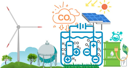
:There is a significant push to reduce carbon dioxide (CO2) emissions and develop low-cost fuels from renewable sources to replace fossil fuels in applications such as energy production. As a result, CO2 conversion has gained widespread attention as it can reduce the accumulation of CO2 in the atmosphere and produce fuels and valuable industrial chemicals, including carbon monoxide, alcohols, and hydrocarbons. At the same time, finding ways to store energy in batteries or energy carriers such as hydrogen (H2) is essential. Water electrolysis is a powerful technology for producing high-purity H2, with negligible emission of greenhouse gases, and compatibility with renewable energy sources. Additionally, the electrolysis of organic compounds, such as lignin, is a promising method for localised H2 production, as it requires lower cell voltages than conventional water electrolysis. Industrial wastewater can be employed in those organic electrolysis systems due to their high organic content, decreasing industrial pollution through wastewater disposal. Electrocoagulation, indirect electrochemical oxidation, anodic oxidation, and electro-Fenton are effective electrochemical methods for treating industrial wastewater. Furthermore, bioenergy technology possesses a remarkable potential for producing H2 and other value-added chemicals (e.g., methane, formic acid, hydrogen peroxide), along with wastewater treatment. This paper comprehensively reviews these approaches by analysing the literature in the period 2012–2022, pointing out the high potential of using electrolytic cells for energy and environmental applications.
1. Introduction
In the past century, most of the world’s primary energy consumption has been based mainly on non-renewable energy sources, such as burning fossil fuels, which causes carbon dioxide (CO2) emissions. Using those energy sources has accelerated global warming, endangered the ecological balance, and, consequently, brought economic and political crises [1,2]. Thus, renewable energy represents a bright future for humanity because it is based on clean and sustainable resources, such as the sun, wind, and water [3]. However, these have transient characteristics, which require proper energy management and storage [4]. There is a substantial drive to develop new and cheaper fuels from renewable energy sources that can be used to substitute the current oil-derived fuels for electricity production, as well as solutions for decreasing CO2 concentration in the atmosphere [2,5].
The electrical energy produced using photovoltaic systems is a sustainable energy resource. However, it must deal with constant changes in sunlight illumination, which can be more or less intense according to the geographic location, season, and period of the day (morning, afternoon, or evening). Thus, storing the energy in batteries or high-energy materials, such as hydrogen (H2) gas, is essential. In fact, the concept of the “Hydrogen Economy” is based on the outstanding properties of this energy carrier, including its high heating value [3,4,6]. As a result, suppose H2 is generated from renewable energy sources (e.g., wind, solar, hydro, and biomass) and used for energy production in the catalytic combustion process. The energy life cycle would not pollute nature because burning H2 only produces water [7]. Another advantage of H2 as an energy carrier is that it can be made from water and electricity using water electrolysis [4].
In addition, several technologies are available for H2 production with associated greenhouse gas (GHG) emissions, including the reforming, decomposition, and hydrolysis of fossil fuels [4]. On the other hand, water electrolysis involves passing an electric current through water to split it into hydrogen (H2) and oxygen (O2) [3]. This technology has the advantage of producing H2 without GHG emissions and being compatible with renewable energy sources [6]. Further, the O2 produced is ultrapure and can be employed in hospitals and life support systems in submarines, aircraft, spaceflight, and diving [1,2].
Approximately four billion tonnes of H2 are required worldwide annually. In addition, less than 5% of this value is produced from non-fossil fuel sources [4]. H2 gas has been used in many fields since the late 19th century, such as the commercial, military, and industrial sectors [8]. More specifically, due to its properties as a reducing agent, it is used in oil refining, in the chemical and food industries for fat hydrogenation, and in metal machining to avoid oxidation. Furthermore, H2 can be used as an energy carrier in fuel cells, which convert H2 and O2 directly into clean electrical power (with zero emissions) more efficiently than internal combustion engines [9].
Issues related to CO2, universally believed to be the primary GHG, have become the focus of global attention because of its substantial emission and consequent adverse effect on climate [10]. The measures for reducing CO2 concentrations concern CO2 capture, storage (e.g., as a solvent or working fluid and even as a storage medium for renewable energy), and conversion (used as a feedstock for chemicals). The CO2 gas conversion is the more sustainable route because it can reduce CO2 accumulation in the atmosphere and produce fuels and valuable industrial chemicals, such as carbon monoxide (CO), formate, alcohols, and hydrocarbons. This allows a carbon-neutral cycle to provide energy without increasing the environmental CO2 concentration [2,10]. Various CO2 conversion solutions have been proposed and extensively studied in the past few decades, including photochemical, thermochemical, electrochemical, photoelectrochemical, and other procedures [2]. The electrochemical process can be performed at room temperature and ambient pressure, thereby increasing the feasibility of reducing atmospheric CO2.
Furthermore, this process is highly controllable and can achieve much higher conversion efficiency, making it advantageous in terms of practicability and industrial prospects [10]. The electrochemical reduction process proceeds through the exchange of electrons between reactants at an electrode surface. Notably, the required electricity could be taken from renewable energy sources, including solar, wind, and geothermal. This reaction process does not produce any new CO2 or contaminants and, consequently, is entirely green [2].
Recently, biomass and biopolymers have been introduced as promising substitutes for non-renewable fossil feedstocks for the sustainable production of fuels and chemical products [2,6]. The thermochemical conversion of biomass can be divided into three processes: gasification, pyrolysis, and liquefaction. Further, direct liquefaction is an effective process for the conversion of biomass into liquid fuels [1,11]. The second-generation biofuels produced from lignocellulosic wastes and lignocellulosic by-products can offer the potential to provide novel biofuels. However, bio-oils, bio-crudes, or polyols obtained via the liquefaction of biomass can be upgraded to gasoline and diesel-like fuels and various polymeric materials [12].
The process of organic molecules’ electrolysis has gained some attention as a potential method for producing H2 onsite. Using organic molecules as a carbon source consumes less electricity because the thermodynamic potential for electrooxidation of those molecules is significantly lower [6]. Apart from biomass, other carbon sources have been studied to produce syngas through electrolysis, such as carbon/graphite electrodes. In addition, syngas is essentially a mixture of H2, CO, and CO2 and can be used as an intermediate product of synthetic fuels (liquid or gaseous), chemicals, and power [1,5]. Generally, syngas can be produced by reforming natural gas, biomass, and coal gasification [1]. However, the synthetic fuel produced from renewable H2 is currently not economically competitive compared to fossil fuel derivatives [5].
Another environmental concern is the industrial pollution from the wastewater produced. The wastewater generated from industries is usually very toxic and polluting; consequently, it needs treatment before disposal to meet the prescribed standards [13,14]. Electrochemical methods, such as electrocoagulation, indirect electrochemical oxidation, anodic oxidation, and electro-Fenton, have been effective in treating industrial wastewater. Furthermore, it is also possible to produce H2 from wastewater and accomplish pollutant treatment simultaneously through microbial electrolysis cells (MECs) [14]. This bioenergy technology holds remarkable potential for the production of H2 and other value-added chemicals (e.g., methane (CH4), formic acid (HCOOH), and hydrogen peroxide) and for wastewater treatment. An exoelectrogenic microorganism oxidises the organic matter in wastewater, releasing protons (H+) and electrons (e−). The membrane and an external circuit transfer them to the cathode side. The protons are then reduced at the cathode to form H2 [15].
The above topics are comprehensively overviewed in the following sections of this review paper.
2. Methodology
A few review papers have partially discussed the use of electrolytic cells, their types, and operation conditions for water electrolysis, CO2 reduction, and wastewater treatment. However, little attention has been given to the potential of using these cells for electrochemical synthesis. From the authors’ perspective, the outstanding growth of new applications taking advantage of the paired electrochemical processes occurring on electrolytic cells should be aggregated. Thus, acknowledging the complexity and interdisciplinarity of this area, an up-to-date review has been designed.
This work aims to identify the trends in using electrolytic cells for energy and environmental applications and where we currently stand with the published research. As a checklist, the review aims to identify the main processes in water electrolysis and discusses the production of H2 and other chemical fuels. Using the Scopus database, the study covers a 10-year range from 2012 to 2022.
The review is divided into four main sections, starting with water electrolysis (and co-electrolysis), followed by electrolysis of organic solutions, a discussion on the electrocracking concept, and finalising with the electrolysis of industrial wastewater. In more detail, the work overviews water electrolysis technologies, namely alkaline water electrolysis (AWE), proton-exchange membrane (PEM) electrolysis, anion-exchange membrane (AEM) electrolysis, and solid oxide electrolysis cell (SOEC). Another point of interest in the study is the electrochemical reduction of CO2 to produce chemicals such as CO, formic acid, methanol, formaldehyde, methane, and ethylene, and using bio-oil from biomass liquefaction to produce valuable chemicals and biofuels. Thus, this review intends to clarify the variety of chemicals and applications produced by electrolysis technologies and discuss future challenges for industrial applications.
3. Water Electrolysis
Water electrolysis is a well-established technology widely used in many industries. This phenomenon was first observed in the 1800s by William Nicholson and Anthony Carlisle and progressed rapidly [16,17]. It consists of water’s electrolytic splitting into H2 and O2 [18], occurring according to the half-cell reactions and the overall reaction expressed in Equations (1)–(3).
Anode: H2O → ½ O2 + 2 H+ + 2e−
Cathode: 2 H+ + 2e− → H2
Overall: H2O → H2 + ½ O2
Table 1 shows several electrolysis systems developed for water electrolysis. Different electrode materials, electrolytes, and operating conditions are used in each system [19]. The main technologies are alkaline water electrolysis (AWE), proton-exchange membrane (PEM) water electrolysis, anion-exchange membrane (AEM) water electrolysis, and the solid oxide electrolysis cell (SOEC). All these technologies are appealing and promising for application in a sustainable hydrogen economy.
AWE is the most mature water electrolysis technology, as it was the first implemented on an industrial scale [4]. It currently holds the highest Technology Readiness Level (TRL, 9–10). The first commercial AWE electrolysers date back to the beginning of the 20th century [4,16,17,20]. Over 200 years after the discovery of water electrolysis technology, AWE electrolysers are still the most widely commercialised [17,21]. AWE runs at temperatures below 100 °C and has moderate efficiency, ranging from 59% to 70% [4,22]. The main advantage is the lower cost due to non-noble electrodes’ use and the long-term stability [4]. The disadvantages are electrolytic corrosion, gas permeation, and slow charge response [22].
PEM water electrolysis is a TRL 8–9 technology, worldwide commercialised, and has a place in the market due to its employment in specific application niches [23,24]. PEM electrolysers are composed of two electrodes pressed against a proton-conducting polymer electrolyte membrane, thus forming a membrane electrode assembly (MEA). The membrane is cation-selective and impermeable to gases, avoiding H2 and O2 crossover [25]. The most common PEM is Nafion, a membrane produced by DuPont de Nemours, Inc. and consisting of a perfluorinated polymer with a functional sulfonic acid end-group. The first PEM electrolysers became commercially available in the 1960s and were developed by General Electric Co. (USA) [18]. PEM electrolysers work at temperatures below 100 °C and offer high efficiency (>80%) [4,22]. These characteristics are advantageous since they allow compact, robust, and stackable cell designs with minor safety issues. However, the acidic environment hinders the kinetics of the redox reactions, thus requiring noble metal catalysts and expensive materials for the bipolar plates and polymeric membranes [4].
AEM water electrolysis is an emerging technology with high efficiency (67–74%). In AEM electrolysers, the AEM allows the transfer of hydroxyl ions from the cathode to the anode and, simultaneously, separates the produced gases. The electrolyte can be 1 M KOH, 30–40 wt.% KOH, 1 wt.% K2CO3, 1 wt.% (K2CO3 + KHCO3), ultrapure water, or deionized water, which greatly influences the electrolyser performance [25,26,27,28,29]. AEM electrolysis technology has a maturity level of TRL 5–6 since it has started being used in small commercial applications and is still under development [30].
The SOEC technology uses solid oxide ceramics as electrolytes. These oxides typically can conduct oxygen ions (O2−), but oxides with protonic (H+) conductivity have also been realised recently. Due to favourable thermodynamics and kinetics, SOEC technology operates at high temperatures and can provide high efficiency (90%) at a lower total cost than conventional low-temperature electrolysis [4,22]. Moreover, the operating temperatures allow the simultaneous electrolysis of CO2 and H2O to produce synthesis gas [4]. However, selecting appropriate catalyst and electrode materials is difficult due to degradation and stability issues. Thus, this process has short operating times and high manufacturing costs [4,22]. This is the main reason this technology still has a lower TRL, between 3 and 4 [4]. The time it will take to be commercially available will mainly depend on the investment of interested companies and government funding programs.
Despite water electrolysis being a promising technology, it still faces various challenges in industrial applications. The most significant disadvantage of commercial and industrial-grade electrolysis systems is their expensive gas production costs. This is due to the electric power demand expense needed to have a large current density to break the water molecules into H2 and O2. The required voltage for splitting a molecule of water is approximately 1.23 V under laboratory conditions. However, in practical electrolysis cells, a higher voltage is required. This is caused by the overpotential level of the electrochemical reaction. This overpotential is affected by many factors, such as electrolyte quality, temperature, pressure, the electrical resistance of the electrolyte, electrode material, separator material, and the applied voltage waveform [8].
3.1. Production of H2
The H2 gas has been referred to as the fuel of the future as it has no carbon and has a higher enthalpy of combustion than any other chemical fuel [31]. Large-scale H2 generation is essential for several chemical and petrochemical industries, as well as the production of synthetic fuels [32]. Presently, over 95% of the H2 output is based on fossil fuels, releasing large amounts of CO2 [19].
The splitting of water into H2 and O2 can be achieved by different processes, such as thermochemical splitting and electrolysis. Pure thermal splitting of water demands extremely high temperatures and, consequently, stable materials and high-temperature thermal energy availability. This is why researchers worldwide try to find alternatives to pure water splitting [32]. Water electrolysis is a good alternative to producing H2 and is mainly used due to its high efficiency and low environmental impact [4,9]. The H2 production for the next few years/decades will undoubtedly be focused on green H2, produced exclusively from water electrolysis powered by renewable energy sources. As the required electricity comes from renewable sources (e.g., solar, wind, geothermal, and hydropower), the process leads to close to zero greenhouse gas (GHG) emissions. Moreover, the process of H2 production can be used as a form of energy storage by using surplus electricity during lower consumption periods and storing it in the H2 molecule.
However, most commercially available electrochemical technologies currently use electricity from conventional power generation technologies with a maximum 40% conversion efficiency and an overall efficiency as low as 30%. H2 production technology has a significant electricity-to-H2 conversion efficiency. Solar, wind, tidal, and geothermal power production technologies have demonstrated high potential for increasing conversion efficiencies, although with considerable capital costs. According to El-Emam et al. (2019), hydropower is the most efficient source-to-power technology (>80%) that is adequate for both pure and hybrid H2 production technologies at a relatively lower cost [32]. So, having electrochemical technology powered by renewable energy sources is expected to enable the scale-up of this zero CO2 emissions process [19]. However, further reduction of the overpotential for H2 evolution remains a challenge for minimising energy consumption during water electrolysis [4].
The lower splitting reaction potential and a reduced electrolyte resistance lead to better electrode surface activity, and higher efficiencies are achieved at higher electrolysis cell temperatures [8]. In addition, running electrolysis at elevated pressure levels improves the process efficiency due to the smaller size of the generated gas bubbles. Consequently, lower ohmic resistance and cell voltage are required. Moreover, electrolysis efficiency has been assessed by applying several voltage waveforms. Results of experimental works show how electrolysis efficiency depends on the applied voltage in direct current power applications and its frequency, pulse width, and amplitude in pulsed and alternating current applications. Mazloomi et al. discuss an optimum combination of those electric variables to reach the highest possible electrolysis efficiency [8].
Vanags et al. [7] studied the kinetics of inductive short-pulse water electrolysis. They concluded that by varying the interelectrode distance and the electrolyte concentration, the electrolysis cell acts like a capacitor when a short voltage pulse (width < 1 μs) is applied. During this short time, the capacitor (i.e., the electrolysis cell) is charged, which can be seen as the charging of the double layer at the cathode/electrolyte interface. Following the short voltage pulse interruption, the energy accumulated in the double-layer capacitor slowly discharges (the pulse discharge tail), activating the electrolysis process. As a result, it was demonstrated that cell charging could be separated from the reactions occurring in the electrolysis process by using short-voltage pulse electrolysis. The kinetics of charging the electrolysis cell with reactive high-voltage short pulses are not affected by the electrolyte concentration. In contrast, the kinetics of the long discharge process do depend on the concentration of the electrolyte, being faster in dilute solutions and slower in concentrated solutions. Vanags et al. also explored the effect of the electrode material on short reactive voltage pulse electrolysis using platinum (Pt) and tungsten electrodes [7]. Experimental results showed that the voltage and current characteristics of inductive voltage short pulse electrolysis are the same for both metals. Still, the concentration of dissolved H2 grew faster at the tungsten electrode. The delay in releasing H2 on a Pt electrode is explained by the tendency of Pt to adsorb H2 gas bubbles on its surface. The current efficiency of 50% was recorded in high-voltage reactive short-pulse electrolysis, while the energy efficiency was in the 70–100% range [7].
Patel et al. [33] studied H2 generation through electrolysis using graphene-carbon nanotube (GC) nanocomposite electrodes. To determine the electrocatalytic activity of GC composites, these were used as the working electrode (WE, A = 0.785 cm2) for alkaline water electrolysis in a three-electrode cell containing 1 M sodium hydroxide (NaOH), a Pt wire counter electrode (CE), and a saturated calomel electrode (SCE) as a reference. The results revealed that the GC73 (70 wt.% graphene and 30 wt.% CNT) nanocomposite was an optimum anode material for water splitting, reaching the highest H2 production rate of 487 L h−1 m−2. Patel et al. [33] claimed that the high H2 production was attributed to defect sites in composites that lowered the local electron density, thus decreasing the activation energy when OH bonds directly with carbon atoms. The work demonstrated the potential application of carbon nanostructures for H2 production using graphene-CNT composites.
Kovac et al. [34] constructed an alkaline electrolyser consisting of three cells connected in a stack. Three bipolar plates, with the anode features on one side and the cathode features on the other, divided the cells. Ni metal foam was used as the electrode material in this design to secure the 3D flow of a 25 wt.% potassium hydroxide (KOH) electrolyte. The type of membrane used was made of Zirfon®, allowing ions to flow and separating the produced gases to avoid their reaction. This study applied a cell voltage between 4 and 10 V that produced currents up to 35 A. Kovac et al. produced 1.138 gH2 h−1 with this bipolar triple cell, while the single cell type produced only 0.25 gH2 h−1 [34].
Palhares et al. [20] studied H2 production using alkaline water electrolysis connected to a photovoltaic panel (20 W). The electrolyser cell was an acrylic cylinder with AISI 304 stainless steel electrodes and a NaOH solution as the electrolyte. The maximum H2 production was achieved with 5 M NaOH and 3.4 V electric voltage at 25 °C. In this study, Palhares et al. produced approximately 2 L of H2 within 4 h of operation and an average irradiance of 800 W m−2 [20].
Yuzer et al. [35] studied H2 production via electrolysis with ion-exchange membranes, including AEM, CEM, and bipolar membranes (BPM). This study used a modified electrodialysis cell with a graphite bipolar plate as the anode (64 cm2) and perforated AISI 304 stainless steel (29 cm2) as the cathode. The results demonstrated that the BPM membrane could produce a stable current density value as high as 20 mA cm−2 and H2 production of 11.4 mmol h−1. This value decreased to 7 mA cm−2 when monopolar ion-exchange membranes (AEM or CEM) were used. However, the BPM membrane has the lowest energy and exergy efficiencies, at 55% and 45%, respectively. The highest energy and exergy efficiencies (82% and 68%, respectively) were found for the reactor configuration using the AEM [35].
Barco-Burgos et al. [22] carried out an experimental study on H2 generation at atmospheric pressure using photovoltaic solar panels as an energy source for the electrolytic reaction. This study analysed the efficiency of H2 production in an alkaline electrolysis cell containing 316 L stainless steel sheet electrodes, a 40 wt.% KOH electrolyte solution, and a low-cost polyester fibre membrane. The experimental results of the H2 flow rate for the several tested electric currents showed that increasing the electrolyser’s current increased the generated H2 flow rate. It was observed that the H2 flow rate gradually increased until reaching a maximum of 0.026 Nm3 h−1 for a current of 30 A and an interelectrode distance of 3 mm. The electrolyser reached a maximum performance of 31% at 5 A, or 4.6% for the whole system comprising a 360 W solar panel [22].
3.2. Production of Syngas
Syngas is a mixture of H2, CO, and CO2 [5]. This gas is a flexible feedstock that allows the production of various synthetic fuels, such as CH4 (Figure 1) [9].
Previous studies show that the co-electrolysis of H2O and CO2 in SOECs is a promising technology for producing syngas. However, in addition to the disadvantages of SOECs previously discussed, there is still a need for additional fundamental research on the identification of the exact mechanisms, providing input for designing more active and stable materials for this process [4]. A recent discovery that resulted in a Portuguese patent [36] demonstrated that alkaline water electrolysis using carbon/graphite electrodes, without gas separation, could produce syngas in a single step at an economic cost [5]. Guerra et al. [5] studied syngas production through water electrolysis on a prototype that consisted of four parts. These were a polycarbonate electrolyte vessel, a Teflon water electrolyzer, a power source, and the measuring system to record the syngas flow rate. The electrodes were graphite discs with a diameter of 5 cm and a thickness of 0.5 cm and a volume of ca. 9.8 mL for the electrolyte solution. The electrolyte solution (NaOH or KOH) fed the electrolyser from the bottom, and the generated syngas exited from the top. The syngas was fed to the flow rate measuring system or to a gas analyzer to measure its composition. The reactions for syngas production occurring on the anode (Equations (4)–(6)) and cathode (Equations (7) and (8) sides are as follows [5].
4OH− → O2 + 2H2O + 4e−
2C + O2 ↔ 2CO
2CO + O2 → 2CO2
2H2O + 2e− → H2 + 2OH−
CO2 + H2 ↔ CO + H2O
The electrolyte concentration and the electric potential were the parameters with the most influence on the composition of the generated syngas. The experimental results showed a maximum CO yield of 7.7 (±1.0)%, together with a CO2 and O2 yield of 2.0 (±1.0) and 8.9 (±1.0)%, respectively, and an H2:CO ratio of 10.6. A gas flow rate of 2.67 L h−1 was attained for a current of 2.45 A, leading to an energy consumption of 460 Wh L−1. These results were obtained using a two-graphite electrode electrolyser in 0.4 M NaOH at 35 °C and a potential of 5 V [5].
Fernandes et al. studied water electrolysis for syngas production using graphite electrodes [37]. The work was carried out in an undivided planar cell with a 25 cm2 geometrical area of graphite electrodes. The conditions were extrapolated for a 45 W prototype employing a 5-cell graphite stack with a total anode geometric area of 150 cm2. The prototype allowed for electrolyte recirculation, temperatures up to 80 °C, and pressures up to 1 bar. The prototype was run using the best conditions found with the lab cell to maximise gas production, regarding electrode spacing, solution pH, and applied potential [37]. For alkaline conditions, the gas obtained at 60 °C was composed of 64% H2, 3.8% CO2, 2.4% CO, and 13.2% O2, as determined by gas chromatography, with a production rate of 100–133 mL min−1 at 22.2 V and 2 A. The prototype was evaluated in 1 M sulphuric acid (H2SO4) due to the possibility of graphite corrosion in acid media. Polarization curves showed substantial differences in the regions corresponding to activation and ohmic resistance when compared to alkaline media. The potential necessary for the aimed current density was 60% of that needed for alkaline electrolysis. The gas composition was also favourable since the O2 concentration decreased to 3%, together with a 17.6% increase in the CO2 concentration. The CO and H2 concentrations were 1.8% and 72%, respectively. Results also suggested the existence of short-chain hydrocarbons in the syngas, including CH4, C2H6, and C2H4, even at 50 °C [37].
Guerra et al. [9] developed a 1 kW prototype for syngas production through water electrolysis. This prototype consisted of two stacks running in parallel but separately. One stack used Schunk electrodes with 10 cells, comprising 11 bipolar graphite electrodes. The other stack used Carbon Lorraine electrodes, with 5 cells containing 6 bipolar graphite electrodes with an interelectrode distance of 3 mm. The bipolar electrodes had a diameter of 114 mm (100 cm2 area) and a thickness of 5 mm for the Schunk arrangement and of 10 mm for the Carbon Lorraine arrangement. The electrolyte solution (0.4 M NaOH) and the generated syngas were circulated in the electrolyser as described in previous work by the same authors [5]. Several tests were conducted to optimise the syngas production process, changing the temperature, pressure, current, voltage, and the graphite electrodes (Schunk and Carbon Lorraine). A good compromise between these parameters was achieved with carbon-lorraine electrodes. The conditions were 5 bars, 3.5 V per cell, a current density of 0.150 A cm−2, a gas flow of 1.17 mL cm−2 min−1, and temperatures between 75 and 80 °C. An important note is that the electrodes have a carbon consumption of around 0.54 g L−1 CO2, which is considered not significant, which means that the carbon electrodes have a long lifetime. Guerra et al. [9] suggested that the electricity consumed in the electrolyser would come from renewable sources, such as solar or wind, and the graphite electrodes could be replaced by renewable carbon sources, such as liquefied biomass. For that reason, Section 4 introduces organic solutions, such as lignocellulosic materials, in electrolysis technologies. Table 3 summarises some of the tested conditions for syngas production by alkaline water electrolysis using graphite electrodes.
4. Electrolysis of Organic Solutions for H2 Production
Caravaca et al. studied the production of H2 from the electrolysis of lignin in alkaline aqueous solutions using a small-scale polymer electrolyte membrane electrolyser (Baltic fuel cells®) [6]. The anode/membrane/cathode components were inserted between Teflon gaskets to seal the cell properly. The current collectors consist of graphitic bipolar plates with parallel flow channels. Bimetallic Pt-Ru (50Pt-50Ru wt.%, unsupported catalyst, 2 mg cm−2) was impregnated on carbon cloth (with a 410 μm thick microporous layer) to make the anode. The cathode was composed of a Pt/C catalyst (20 wt.% Pt, 0.2 mg cm−2) impregnated on a similar carbon cloth. The geometric surface area of both electrodes was 25 cm2. An alkaline (OH−) conductor polymeric membrane (Fumapem FAA-3–50®) was used as the electrolyte. The lignin alkaline solution (10 g L−1 lignin, 1 M NaOH, 2.5 mL min−1) was continuously supplied to the anode of the electrolysis cell, whereas a 1 M NaOH solution (2.5 mL min−1) was fed to the cathode [6].
During electrolysis, the applied cell voltage promoted the cathodic electroreduction of H2O, generating H2 and OH−, with the latter ions migrating through the ion-conducting membrane to participate in the electrooxidation of lignin at the anode (Figure 2). Experiments were run at 80 °C, and the applied cell voltage ranged between 0 and 0.9 V. A lignin-NaOH, or NaOH solution, was fed during the experiments to keep the concentrations steady [6].
Caravaca et al. observed that no electric current was recorded during water electrolysis experiments in the selected voltage window (0–0.9 V). This could be explained by the fact that the thermodynamic cell voltage for water electrolysis to occur at this temperature is approximately 1.2 V. Conversely, when lignin solutions were supplied to the anode, the current showed a linear relation with the applied cell voltage for voltages above ca. 0.45 V [6]. This confirmed that H2 could be obtained by electrolysis of organic molecules at significantly lower voltages than water electrolysis because of the reduced thermodynamic voltage of the former (0.21 V). The maximum H2 production rate achieved was 0.54 mL min−1. It was also observed that increasing the reaction temperature from 30 to 90 °C led to a gradual increase of the lignin electrolysis currents and, consequently, of the H2 flow. A maximum current density of 3.6 mA cm−2 was recorded at 90 °C [6]. Consequently, the kinetics of the electrolysis of lignin, being a complex molecule, were significantly slower. Caravaca et al. stated that this was related to the cleavage and rupture of the complex bonds of this biopolymer. The authors highlighted that, though the produced H2 flow was relatively low, this research demonstrated the high potential of using biomass residues for H2 production through direct electrochemical conversion in a continuous-flow polymer electrolyte membrane reactor. This promising process requires better electrocatalytic activities, which may be achieved by developing highly active anode catalysts and optimising the operating conditions. This may open a new electrochemistry field as an alternative to the traditional catalytic route that requires high reaction temperatures and pressures [6].
Hibino et al. studied H2 production by direct lignin electrolysis. Tests were conducted by feeding a mixture of lignin with 85 wt.% H3PO4 to the Pt/C anode compartment in a batch cell operating between 100 and 200 °C [38]. Results showed that the currents recorded at each voltage and temperature were higher in the presence of lignin in the acidic solution, becoming more significant for higher temperatures. The ohmic resistance exhibited minimal dependence on temperature because of the low activation energy related to proton conduction in the electrolyte. On the other hand, the polarisation and mass-transfer resistances were lower for higher temperatures. The lignin oxidation was also evaluated during the mixture electrolysis in the 0–100 mA cm−2 range. This analysis found that CO2 was the primary oxidation product from lignin anodic polarisation. This suggests that C4–C7 aromatic and aliphatic molecules resulting from lignin decomposition were converted into CO2. For this process, the presence of water in the anode was essential. Further, filtrate and gas analyses determined that H3PO4 acted as a lignin degradation catalyst and as a water source for the anodic reactions. Data on the H2 evolution rate agreed well with the theoretical values (up to 0.34 mL min−1) within the tested temperatures, demonstrating a current efficiency close to 100%. Lastly, it was observed that electrolysis was enhanced using a thinner membrane and a PtFe/C anode instead of a Pt/C anode [38]. As the electrolysis cell exhibited efficiencies in the 83–91% range, the study demonstrated H2 production by direct lignin electrolysis as a viable process [38].
Ruiz-López et al. studied a new concept based on an alcohol electrolyser to achieve over-faradaic H2 production rates [39]. This experiment was run in a polymer electrolyte membrane electrolysis cell with commercial palladium (Pd) supported on Vulcan XC-72 (20 wt.% Pd/C, Alfa Aesar) and commercial Pt on carbon black (20 wt.% Pt/C, Alfa Aesar) as the cathodic and anodic catalysts, respectively, with a geometric electrode area of 6.25 cm2, and using an AEM (Fumapem FAA-3-50, Fuel Cell Store). The operation conditions in the electrolysis reactor were 65 °C, 0–1.2 V, and 0–0.5 A for 8 h. Firstly, it was observed that methanol electrolysis in alkaline media (1 M MeOH + 1 M KOH) allowed an over-faradaic H2 production rate when the solution was simultaneously fed to the anodic and cathodic compartments of the electrolyser. As a result, cathodic H2 production attained faradaic efficiencies of up to 145%. This was due to the coexistence of the electrochemical H2 evolution reaction and the catalytic dehydrogenation of methanol (Figure 3). The former reaction enables faradaic H2 production, and the latter allows for extra H2 output, boosted by the electrochemical promotion of the catalytic reaction. In addition, the K+ ions promoted the chemisorption of intermediate species on the active Pd sites, triggering H2 production from the dehydrogenation of methanol [39]. Considering the overproduction of H2, this cell design enables a significantly lower energy consumption per unit of generated H2 compared to traditional alcohol electrolysis configurations [39]. The results demonstrated the possibility of attaining “over-faradaic” H2 production, crucial for boosting the energy efficiency of H2 generation through electrolysis of organic molecules [39].
Yang et al. studied H2 production through electrolysis with native biomass catalysed by the Fe3+/Fe2+ redox couple in a PEM electrolyser [40]. The cell was constituted by two graphite plates separated by a Nafion 115 membrane. The anode graphite plate had embedded graphite felt, and the cathode comprised a 5-layer gas diffusion electrode (GDE, FuelCellsEtc, USA). The anolyte was a mixed solution of biomass (starch, cellulose, and glucose) and ferric chloride (FeCl3), and the catholyte was a 1 M H3PO4 solution. The Fe3+/Fe2+ redox couple played two critical roles in the electrolysis process. The Fe3+ ion acted as an oxidation agent for biomass degradation, whereas the Fe2+ ion worked as a charge carrier, transferring electrons to the cell anode to produce H2 at the cathode (Figure 4) [40].
In order to evaluate the reliability of the biomass-Fe-based H2 evolution system, Yang et al. established a temperature of 90 °C at which Fe3+ could oxidise the biomass [40]. Three tested currents (50, 100, and 200 mA cm−2) showed similar curves for all types of used biomass. Furthermore, for the same current density, the rate of H2 evolution was identical, and all experiments reached a high faradaic efficiency of ca. 91% [40]. Analyzing the products formed after the electrolysis process, it was observed that the large molecular-weight polymeric biomass could be oxidised to low molecular-weight derivatives. Although the study involved different types of biomass, the final products always included HCOOH and acetic acid. CO2 was the only gas product at the anode, whereas the only product at the cathode was H2. Lastly, it was observed that the increase in temperature and electrolysis time increased the amount of HCOOH and acetic acid, thus evidencing the decomposition of the native biomasses [40].
Yang et al. concluded that, compared to regular PEM, their biomass-Fe ion electrolyser could convert biomass to H2 at a lower potential (H2 began to be produced at 0.7 V) without requiring noble metal catalysts on the graphite felt anode [40]. The electricity consumed in the glucose-Fe ion system experiments was 1.845 kWh Nm−3 H2 at a current density of 100 mA cm−2, saving ca. 60% of the electricity required for typical alkaline water electrolysers, specifically 4.7 kWh Nm−3 H2 at 2 V and 100 mA cm−2 [40]. Table 4 summarises the different tested conditions for H2 production by electrolysis of organic solutions.
5. Elesctrocracking Concept
The electrocracking concept is linked to the fact that electricity can be applied directly to initiate other chemical reactions, such as the breakdown of bio-oil into low-carbon aromatics and light olefins. In addition to reducing the oxygen content and increasing the hydrogen content and heating value of bio-oil, this process also produces H2 as a by-product [41,42].
5.1. Production of Syngas
Guerra et al. studied the production of syngas using an aqueous mixture of liquefied cork biomass and NaOH [1]. The study used a lab-scale prototype comprising the electrolyser to form syngas, coupled with a cylindrical tank containing the electrolyte solution, and another cylindrical tank packed with a molecular sieve to dry the produced gas. The electrolyte vessel was made of stainless steel and methyl methacrylate polymer, and the electrolyser comprised nine steel disc electrodes with a total area of 20 cm2, with two channels for electrolyte circulation. The channels were used for the electrolyte input and output, allowing flow of the generated gases, and the interelectrode distance was 0.4 cm. Tests were run for 2 h while recording the current over time [1].
The minimum cell voltage allowing gas production was found to be ca. 6 V. However, it was found that the required voltage was reduced for higher temperatures. Furthermore, it was observed that higher temperatures up to 70 °C favour CO generation. The optimum operational conditions determined by Guerra et al. comprised the use of 1.2 M NaOH mixed with 20 vol.% liquefied cork electrolyte [1]. The used operating conditions (Table 5) led to a syngas composition of 66.7% H2, 25.3% CO, and 8.0% O2 (no CO2), produced at a flow rate of 138.5 mL min−1, and consuming 7.75 Wh L−1. Some residual biomass was deposited at the stainless steel electrodes, exhibiting changes compared to the initial biomass structure. This was a significant result, as it allowed the oxidation of liquefied wood into CO [1].
5.2. Electroreduction of CO2
The CO2 gas is a GHG, and, therefore, using renewable energy to convert it to transportation fuels and commodity chemicals is a value-added approach to simultaneously generating products and reducing carbon emissions [43] (Figure 5). The electrochemical CO2 reduction process is one of the promising methods to produce chemicals such as CO, HCOOH, methanol (CH3OH), formaldehyde (HCHO), CH4, ethylene (C2H4), and some other products [2,44]. The process involves a gain of electrons at the cathode surface without using redox agents. The electricity can come from renewable energy sources without producing new CO2 [2]. Equations (9)–(14) describe possible cathodic processes occurring during the CO2 reduction reaction (CO2RR).
2H+ + 2e− → H2
CO2 + 2H+ + 2e− → CO + H2O
CO2 + 2H+ + 2e− → HCOOH
CO2 + 6H+ + 6e− → CH3OH + 2H2O
CO2 + 8H+ + 8e− → CH4 + 2H2O
CO2 + 12H+ + 12e− → C2H4 + 4H2O
The typical catalytic system for the CO2 electrochemical reduction is composed of four components: a catalyst-coated cathode and anode for the CO2RR and O2 evolution reactions, respectively, an electrolyte for fast mass transport of both reactants and products, and a polymer electrolyte membrane separating the electrodes. During the electrolysis process, the ions cross the electrolyte membrane, and electrons flow through the external circuit [2].
Although CO2 electroreduction is a promising process, many issues still need to be overcome, including high overpotential, low current density, low selectivity for specific products, low catalyst stability, and the competitive hydrogen evolution reaction (HER). The efficiency of the process can be enhanced by developing highly effective electrocatalysts, increasing CO2 pressure, modifying electrolyte concentrations, or using more effective cell configurations [2].
Different types of cells are applied to this field, such as the H-type cell (Figure 6), polymer electrolyte membrane flow cell, microfluidic cell, differential electrochemical mass spectrometry (DEMS) cell, and the SOEC. The H-type cell is the most frequently used in laboratory studies to evaluate catalysts’ performance in aqueous electrolyte solutions and is adequate for gas and liquid products. However, industrial applications require a cell design with lower resistance and higher mass transport efficiency [2].
Additionally, the polymer electrolyte membrane flow cell (Figure 7) design is the most common for industrial applications, given that it meets these characteristics [2].
The microfluidic cell types are also used to assess the catalysts’ performance during CO2RR. The SOEC can be used to co-electrolyze water and CO2 (Figure 8). It works at high temperatures (>600 °C) and can achieve high efficiencies without using precious metal catalysts.
The DEMS (Figure 9) is an analytical technique that separates and collects electrochemical reaction products in real-time and analyses them rapidly [2].
The electrolytic cell design for electroreducing CO2 is getting closer to achieving industrial applications [2]. This fact was reinforced by Masel et al., who collected information about the accomplishments in this scientific field and industrial applications until now. Masel et al. demonstrated the different industrial applications of CO2RR and introduced vital benchmarks and the state-of-the-art, as presented in Table 6, Table 7 and Table 8 [45].
5.3. Production of Formic Acid (HCOOH)
HCOOH is a simple yet strong organic acid with prominent advantages. It is more eco-friendly, noncorrosive, and biodegradable than other organic and inorganic acids. It can be used to produce chemical and energy-related products (Figure 10). HCOOH is broadly applied in agriculture, rubber, pharmaceuticals, animal feeds, leather, and textile industries. Related to energy production, it can directly produce or be upgraded into a variety of high-quality fuels, including H2, CO, or methanol. Especially, HCOOH is regarded as a promising H2 storage material [46].
As mentioned, the H-type cell does not achieve high performance for the CO2RR. This is explained by the fact that in this type of cell, CO2 has to dissolve in an aqueous electrolyte, and this gas has low solubility in aqueous solutions at ambient temperature and pressure. Further, Malkhandi et al. introduced two solutions for this problem: filling the H-type cell with high-pressure CO2 or using a GDE. However, this work focused only on the study of GDE use for the electrochemical conversion of CO2 to high-value chemicals. GDE consists of an electrically conducting porous support layer and a micro-porous gas diffusion layer whose interior wall is coated with a catalyst (Figure 11) [44].
In an electrolyzer, the GDE is located between the gas and electrolyte compartments. That way, the bulk electrolyte and CO2 will not considerably mix to form carbonates. Thus, alkaline electrolytes, which have been demonstrated to improve C2 products, can be used without mass transport limitations. Furthermore, the GDE can be used with liquid electrolytes and can also be used with solid electrolytes (Figure 12) [44].
Malkhandi et al. argued that the reduction of CO2 can become a competitive method for producing valuable chemicals without a fossil fuel footprint if the conversion efficiency of electric energy into chemical energy is higher than 60% (specifically for CO, ethanol, and ethylene production) [44]. The GDE’s disadvantage is that it has to be monitored for its entire life. Malkhandi et al. state that there are three main factors for low GDE lifetime: catalyst deactivation caused by contaminant poisoning, flooding of GDE pores with electrolyte, and catalyst layer damage due to the rapid release of product gases. Nevertheless, the use of GDE in electrochemical cells for CO2 reduction has been largely studied since it appears to be a promising process [44].
Yang et al. studied the production of pure HCOOH through electrochemical CO2RR [47]. The HCOOH cell consisted of three compartments: a cathode compartment where the cathode operates at a pH of 7–11 using a Sustainion™ anionic membrane ionomer, a centre flow compartment with acidic (pH of 1–5) ion-exchange bead electrolyte media where deionized water flows to remove the HCOOH product, and an anode acid compartment where a Nafion membrane ionomer serves as the electrolyte (Figure 13). The electrochemical cell designed by Yang et al. operated at a current density of 140 mA cm−2 and a cell voltage of 3.5 V with faradaic efficiencies for HCOOH generation up to 94%. This high current density obtained for a relatively low voltage cell was attributed to the use of a GDE cathode and a Sustainion™ anion membrane. High HCOOH faradaic efficiencies were found to be critically dependent on the selection of the cation membrane used on the anolyte compartment side of the cell. Specifically, thicker Nafion® membranes were effective in minimising formate ion crossover losses into the anode compartment. Yang et al. also studied the possibility of two modes of cell operation, a centre compartment single-pass versus recirculation modes, and concluded that the single-pass mode was preferred. The best cell configuration led to a maximum of 9.4 wt.% HCOOH in the centre fluid after 142 h operation [47].
Ramdin et al. [48] used pressurised CO2 to overcome the problem of low CO2 solubility in aqueous solutions, as suggested by Malkhandi et al. [44]. This study aimed to produce HCOOH through CO2RR and study the effect of BPM and CEM on this process’s performance. BPM and CEM performance evaluation was done in a semi-continuous batch electrolyser with an anode of Ir-MMO and a Sn-based cathode. The operation conditions were a cell voltage of 3.5 V at 22 °C and 5–50 bar, with a 10 mL min−1 flow rate, 1 M KOH anolyte, and 0.5 M KHCO3 catholyte for the BPM experiment or 0.5 M H2SO4 for the CEM experiment. For both membranes, it was found that the faradaic efficiency and the current density increase as the CO2 pressure increases, achieving 90% and 30 mA cm−2, respectively. The optimum pressure value for both membranes was 40 bars. This study concluded that BPMs are better than CEMs. This observation is due to the advantages of the BPM, such as allowing the use of two different electrolytes, maintaining a constant pH gradient over time, and lowering product crossover (which implies fewer losses). Ramdin et al. also registered a production of HCOOH up to 2 wt.% at a voltage of 4 V with a current density of 100 mA cm−2; however, values of faradaic efficiency are relatively lower (65%) [48]. Huang et al. introduced the new application of 2D non-metallic black phosphorus nanosheets (BP NSs) in electrochemical CO2 reduction. This study was carried out in a single-compartment, three-electrode cell with electrodeposited (ED)-Bi dendrites/BP NSs as the WE, a Pt plate as the CE, SCE as the reference electrode (RE), and 0.5 M KHCO3 solution as the electrolyte. It was achieved at a maximum HCOOH yield rate and HCOOH faradaic efficiency (FE) of 22.7 μmol dm−3 h−1 and 25.8% at −1.3 V, respectively [49].
Ye et al. studied the performance of an Sn-Cu alloy catalyst in the electroreduction of CO2 to formate. The CO2RR was studied in a 3-electrode system in an H-cell filled with a 0.5 M KCl solution in the cathodic compartment and a 0.25 M K2SO4 solution in the anodic compartment. A Nafion 115 membrane separated these two compartments. The Sn-Cu alloy served as the WE, the CE was a Pt wire, and the RE was Ag/AgCl (3.0 M KCl). Ye et al. concluded that the Sn-Cu alloy suppressed H2 and CO evolution and promoted formate generation with a faradaic efficiency of 82.3% ± 2.1% at −1.14 V vs. RHE. The formate mass activity reached 1490.6 ± 7.5 mA mg−1 at −1.14 V vs. RHE, outperforming Sn-based catalysts. Calculations suggested that the formation of formate on a Sn-Cu alloy catalyst follows the path CO2HCOO* HCOOH [50].
Xiang et al. also studied formate production by CO2 electrochemical reduction. The reactor consisted of a GDE cathode, in which was applied an optimum prepared SnO2/C mass ratio catalyst with a geometric surface area of 2 cm2, a RE-61AP reference, a coiled Pt wire anode, 1 M KOH (Emsure®, 85%), and 5 M KOH solutions as the catholyte and anolyte, respectively, separated by a CEM (F-950, Fumapem) [51]. Under optimised conditions, The faradaic efficiency for formate generation could be kept at ca. 80% in the potential range of −0.63 to −1.43 V (vs. RHE), with overall current densities in the 30–250 mA cm−2 range. The yield of formate reached by Xiang et al.’s [51] experiment was 3 mg min−1 cmWE−2 when applying a cathodic potential of −1.43 V.
A novel HCOOH cell design suggests a potential route for future commercial use of HCOOH as a sustainable chemical feedstock for producing downstream chemicals [52]. Calvinho et al. studied five nickel phosphide compounds (Ni3P, Ni2P, Ni12P5, Ni5P4, and NiP2) as electrocatalysts for CO2RR in aqueous solution. The study observed three different products, HCOOH, methylglyoxal, and 2,3-furandiol, in a sandwich-type electrochemical cell using a Pt anode, a nickel phosphide cathode, a Nafion membrane separator, and a 0.5 M KHCO3 solution as the electrolyte (Figure 14) [52].
Calvinho et al. also confirmed that dissolved CO2 was the carbon source for the three products observed instead of ionised forms of bicarbonate [52]. This means dissolved CO2 is the primary substrate for CO2RR on nickel phosphides. The results showed a faradaic efficiency of 71% for 2,3-furandiol at 0 V vs. RHE with a Ni2P cathode and 5% for HCOOH (despite this compound being produced at all potentials). The reaction selectivity tended towards HER for more reductive potentials (<−0.2 V vs. RHE). It was shown that the reduction of CO2 to 2,3-furandiol and methylglyoxal was predominant from 0.05 V to −0.10 V vs. RHE on the more phosphorus-rich nickel phosphides, with Ni2P giving the highest faradaic yield at the lowest overpotential. Calvinho et al. concluded that transition metal phosphides are the first class of materials (other than enzymes) that can convert CO2 to C3 and C4 products in aqueous media at a near-thermoneutral potential with high selectivity [52]. Table 9 summarises the tested conditions used in different studies on HCOOH production from CO2 electroreduction.
6. Electrolysis of Industrial Wastewater
Electrochemical treatment of waste streams (as shown in Figure 15) has little or no harmful environmental effects because these techniques do not involve using dangerous reagents [54,55].
6.1. Production of H2
Significant amounts of waste are produced in the agricultural, domestic, and industrial sectors [54]. Traditional wastewater treatment methods include physical, chemical, and anaerobic treatment, which are inefficient in producing harmless wastewater. On the other hand, wastewater contains large amounts of organic matter, making it highly valuable in resource utilisation [43]. This unused resource could be a potential source of energy content (17.8 kJ g−1 COD) if efficient and economically viable technologies are available to exploit it [56]. Biological H2 production has several advantages compared to photoelectrochemical or thermochemical processes, due to its low energy requirements and low investment costs [15]. Among the several types of wastewater bio-treatment technology, the bio-electrochemical method is a good way to achieve the goal of harmless wastewater production and resourceful utilisation. This approach is able to both treat wastewater to meet emission standards and produce high-value products. This includes electricity generation from microbial fuel cells (MFC) and H2 production from microbial electrolysis cells (MEC) [55].
The MEC has evolved with significant advancements in producing H2 and other value-added products, such as CH4. Biohydrogen production from MEC has been used with industrial effluents owing to the advantage of energy recovery from waste with simultaneous treatment [15]. MEC includes an anode chamber and a cathode chamber separated by a PEM. An exoelectrogenic microorganism oxidises the organic matter in the wastewater and releases protons and electrons that are transferred to the cathode side through the membrane and the external circuit, respectively. Electrons and protons then combine at the surface of the cathode catalyst to form H2 gas. However, as this process does not occur spontaneously due to thermodynamic limitations, a small amount of electrical energy must be supplied [15]. Still, the specific energy consumption is considerably inferior to the electricity consumed by the H2 production process in water electrolysis [55]. The MEC reactor can be divided into single (Figure 16) and two-chamber versions. The most critical drawback of the single chamber MEC design is that the produced H2 is consumed by microorganisms such as methanogens, electrogens, and homoacetogens, particularly during long-term operation.
The dual-chamber MEC includes a membrane to favour higher H2 recovery and higher H2 purity, and avoid H2 consumption by methanogenic bacteria [56]. In addition, MEC can use various carbon sources, such as domestic and industrial wastewater, to produce H2 and simultaneously reduce the chemical oxygen demand (COD) [15]. Jayabalan et al. [56] investigated the enhancement of biohydrogen production from sugar industry effluent using nanocomposite catalysts coated on a NF cathode in a dual-chamber MEC reactor. Each of the three MEC reactors fabricated was composed of an anodic and cathodic compartment separated by a Nafion®117 PEM from DuPont™, a plain graphite plate as the anode, a copper wire current collector, and a Ni foam cathode coated with a nanocomposite catalyst (NiO.rGO and Co3O4.rGO). The anode and cathode compartments (250 mL) were filled with industrial sugar wastewater and 50 mM phosphate buffer [56].
Furthermore, at an applied voltage of 1.0 V and ambient temperature, the MEC with NiO.rGO/NF attained the highest COD removal efficiency (56.6%), H2 production rate (4.83 ± 0.11 mmol L−1 D−1), and current density (1.16 A m−2). The organic matter conversion in wastewater is the primary mode of H2 generation in the form of splitting (anode side) and combining protons and electrons (cathode side). The transport of the protons and electrons influences the microcellular activity and impacts the COD removal efficiency. Jayabalan et al. [56] concluded that Ni-based catalysts exhibited high activity for HER, suggesting Ni should replace conventional precious metal catalysts.
Spurgeon et al. [15] constructed a new compact design of MEC within an anaerobic digester. The cathode chamber is fitted in the anode chamber in a format similar to the typical dual-chamber MEC for wastewater treatment and H2 generation. Distillery wastewater was used in this study. The MEC was built using a glass bottle for the anodic chamber and a centrifuge tube for the cathodic chamber. A Nafion 117 PEM (Membrane Inc., USA) with an area of 5 cm2 separated the two chambers of the MEC. The anode was a 50 cm2 plain carbon cloth, and the cathode was a 2 cm2 Pt mesh. The anodic chamber contained 450 mL of artificial wastewater composed of sodium acetate, activated sludge, nutrients, minerals, and buffer solution. The cathodic chamber contained 25 mL of phosphate buffer with 50 mM K2HPO4 and 50 mM KH2PO4. The pH of the anolyte was adjusted to 7 using 2 M NaOH, and the pH of the catholyte was set to 7.5 using 0.5 M H2SO4. A titanium wire connected the anode and the cathode for the electronic transfer between the chambers. A variable voltage of 0.6 to 1.0 V was applied to study the effect of applied voltage on H2 generation. The tests were carried out for three days under batch mode operation at 1 atm and 35 °C [15].
A cumulative H2 production of 40.05 ± 0.5 and 30.12 ± 0.5 mL were obtained at current densities of 811.7 ± 20 and 908.3 ± 25 mA m−2, respectively, for the traditional design and the modified MEC system. The cathodic hydrogen recovery (CHR), corresponding to electron recovery as H2, presented a maximum of 46.5 ± 0.8 and 38.8 ± 0.5% in conventional and modified MEC, respectively. The Coulombic efficiency (CE), corresponding to the recovery of total electrons in acetate as current, was 17.25 ± 0.15 and 16.82 ± 0.1% for conventional and modified MEC, respectively. In addition, for traditional and modified MEC designs, the wastewater COD removal efficiency was observed to be 77.5 ± 1.0% and 75.6 ± 1.5 in 70 h. The modified compact design worked effectively to produce H2 under different COD concentrations (increased substrate concentration reduced the COD removal efficiency), anolyte and catholyte concentrations (H2 generation increased with catholyte concentration), and applied potentials (H2 production increased with the potential). In addition, the MEC performance in terms of CHR, CE, and COD removal efficiency for synthetic wastewater and distillery wastewater was compared. For the system operated with distillery wastewater, the results for these three parameters were 33.85 ± 0.5, 13.16 ± 0.2, and 72.5 ± 0.5%, respectively. The synthetic wastewater had higher performance than the real wastewater. According to Spurgeon et al., these results due to to the distillery wastewater containing complex substrates and degradation pathways of exoelectrogenic species. In summary, Spurgeon et al. concluded that the modified compact MEC, a retrofit to existing anaerobic digesters, can extend the use of anaerobic digesters and improve their economics in wastewater treatment [15].
Pathak et al. [53] studied an experimental method combining a solar PV-based electrolysis process and textile dyeing industry wastewater (TDIWW) for H2 production and simultaneous treatment of this wastewater. The typical wastewater from the textile industry is characterised by high ranges of pH, colour, total dissolved solids, total suspended solids, total solids, chloride, biological oxygen demand (BOD), COD, heavy metals, and sodium. The solid consists essentially of diverse organic and inorganic pollutants containing nitrogen, chloride, and phosphate. The ions’ attraction to the opposite charge electrode promotes solid and other pollutant removal. BOD is one of the primary pollutants in TDIWW, affecting aquatic life because of the present chemicals, metals, and other inorganic compounds. Lastly, COD can be removed through electrolysis, as this process promotes the decomposition of organic compounds. The used wastewater had a high BOD (402 mg L−1), which was removed up to 108 mg L−1 (73% removal) with a steel electrode at 12 V [53].
The study of Pathak et al. [53] involved three different electrodes: carbon, steel, and Pt. The carbon electrode had a surface area of 23 ± 1.5 cm2, the steel electrode area was 1.07 ± 0.23 cm2, and the Pt electrode had an area of 0.1 ± 0.02 cm2. The electrolysis process’s efficiency depends on the electrolyte’s ionic strength. As TDIWW has a high conductance and a high amount of total dissolved solids, its ionic concentration was considered sufficient to use it as an electrolyte in electrolysis processes. Furthermore, the wastewater produces more H2 than simple water because of the high content of organics and salts, which enhance the rate of ion formation and result in high H2 production with good pollutant removal efficiency [53].
Results demonstrated that the efficiency of pollutant removal, concerning conductivity, total dissolved solids, total suspended solids, BOD, COD, hardness, total nitrogen, and total phosphorus, ranged from 73 to 96% using steel electrodes at 12 V [53]. Maximum efficiencies of 49.6, 67.8, and 57.1% for carbon, steel, and Pt electrodes, respectively, were found for an input voltage of 3 V. However, for a higher voltage of 12 V, the H2 production rate was higher (0.27 mL min−1) with steel electrodes [53]. Pathak et al. explained that this might originate from an increase in the size of the bubbles, leading to floc formation and increasing the H2 production rate. As this study used a solar PV-based system (less carbon emission), Pathak et al. considered the higher voltage to achieve higher H2 production [53]. This study also analysed the hardness and nitrogen removal. Hardness is related to calcium (Ca2+) and magnesium (Mg2+) presence, and the maximum removal (90.7%) was attained at 12 V, owing to large amounts of flocs formation, as the charge-transfer rate is higher in the presence of hydroxide. Nitrogen removal showed a maximum efficiency of 93.6% with steel electrodes [53].
Consequently, TDIWW electrolysis using solar PV panels with storage systems for constant power supply has proven to be an efficient and energy-intensive approach for wastewater treatment coupled with H2 generation with clear advantages compared to traditional treatment methods [53].
6.2. Pollutant Removal
The treatment of industrial wastewater, especially if it is a mix, is challenging due to its high complexity [57]. With the ever-increasing standard of drinking water supply and the stringent environmental regulations regarding wastewater discharge, electrochemical technologies have regained their importance worldwide. Electrochemical methods are frequently used to treat wastewater containing organic oil, organic pollutants, heavy metals, and nitrate [14]. Some electrochemical techniques include electrochemical metal recovery, electrocoagulation, electroflotation, and electrooxidation [58]. These technologies are interesting because they lead to less sludge generation, are easy to operate, and do not require additional chemicals [58]. Namely, electrooxidation involves decomposing organic materials through oxidation into CO2, water, and other oxides [58]. Specifically, indirect electrochemical oxidation is an environmentally friendly technology that can completely mineralize recalcitrant organic matter, removing nitrogen species, and degrade pollutants through a powerful oxidant at the anodic surface [13].
Kliaugaite et al. [58] studied the electrochemical removal and recovery of humic-like substances from paper and food industry wastewater. The secondary effluent from these wastewaters still contains a high COD and colour intensity caused by complex degradable organic compounds that are primarily humic-like substances (HLS). Humic substances are heterogeneous and polyfunctional polymers formed by microbial decay from plant and animal residues and occur in soils, sediments, and natural waters. HLS consists of a complex, unresolved mixture of relatively small molecules. Streams containing HLS are usually produced in industrial operations involving leather, wood, and food processing.
Kliaugaite et al. [58] performed two continuous mode experiments: membrane electrolysis and electrocoagulation. The electrochemical cell consisted of 2 chambers: a plate electrode with a surface area of 22 cm2 and a flow channel. In the case of the membrane electrolysis experiment, these chambers were separated by a membrane (polyethersulfone microfiltration membrane, AEM, and CEM), and a titanium-coated electrode with 0.5 mg cm−2 Pt/Ir mixed metal oxide as the anode and a stainless-steel electrode as the cathode was used. In the electrocoagulation experiment, chambers were hydraulically connected, and both electrodes were low-cost iron plates [53]. The results indicated that membrane electrolysis and electrocoagulation could play an essential role in the HLS removal and recovery, and the decolourization of coloured wastewater. Compared to membrane electrolysis, electrocoagulation has lower operating costs and efficiently removes colour and COD, making it more suitable for highly polluted wastewater. Electrocoagulation showed removal effects similar to those of membrane electrolysis (65% of colour and 30% COD removal), spending 0.12 kWh m−3 energy consumption, which is 25 times cheaper than membrane electrolysis (3 kWh m−3). Kliaugaite et al. [58] showed that the type of membrane used in these applications does not largely impact the treatment efficiency; however, it was noticed that microfiltration membranes (MFMs) and AEMs are more suitable for wastewater electrolysis than CEMs. Using a CEM, 50% of colour and 10% of COD were removed, while 70% of colour and 20–30% of COD were removed using the other two membranes in the same conditions. So, it was demonstrated that the electrocoagulation treatment process efficiently removes COD and colour [58].
Popat et al. [13] studied a treatment for mixed industrial wastewater (from pharmaceuticals, dyes, textiles, etc.) that consisted of an electrochemical advanced oxidation process (EAOP) followed by a biological process. The EAOP applied in this study was the electro-Fenton process. A total of two anodes (Ti/Pt mesh) and two cathodes (graphite felt) were used for the experiments. The initial value of COD in raw wastewater was 1152 mg L−1, which was possible to reduce to 691 mg L−1 by EAOPs process at optimum conditions: 10 V, interelectrode distance of 1 cm, area of 25 cm2, catalyst loading of 10 mg L−1 and a persulphate dosage of 200 mg L−1. Due to the COD reduction, the BOD/COD ratio increased from 0.34 to 0.52, which proves the enhancement in the biodegradability of the wastewater after EAOPs treatment. However, the COD of any effluent disposed of in any surface water body should not exceed 250 mg L−1. As a result, the electro-Fenton process was followed by a biological process that further reduced the COD to 60.8 mg L−1. The efficiency of this last process of treating wastewater was increased because non-biodegradable organic compounds were converted into biodegradable forms by the electro-Fenton process. As the combined process had a COD removal efficiency of 94%, Popat et al. concluded that the combination of EAOPs and biological treatment seems a feasible and economical option for degrading mixed industrial wastewater [13].
Nidheesh et al. [14] studied the electrochemical treatment of mixed industrial wastewater, specifically electrocoagulation and indirect electrochemical oxidation processes, through COD and colour removal studies. The experiments for electrocoagulation performance evaluation were conducted in a rectangular tank with a working volume of 1 L. Commercially accessible aluminium plates with a 25 cm2 surface area were used as both anodes and cathodes (separated by 1 cm). The experiments were carried out at room temperature. A similar experimental setup was used for the indirect electrochemical oxidation experiments, using commercially available graphite plate electrodes with a surface area of 25 cm2 [14].
Additionally, both processes are more efficient at the wastewater pH, i.e., 7.7. The efficiency of electrocoagulation was assessed at different cell configurations, specifically monopolar and bipolar designs in parallel connection. The results found that the monopolar connection was more effective for COD and colour removal from the wastewater than the bipolar design. The monopolar connection exhibited COD and colour removals of 55 and 56%, respectively, whereas the bipolar connection led to a lower removal of 43 and 48% at the wastewater pH and an applied voltage of 1.5 V for 1 h. In the case of the indirect electrochemical oxidation process using graphite electrodes, the COD and colour removal efficiencies of the indirect electrooxidation process were found to be 55 and 99.8%, respectively. These results were obtained for 1 h of electrolysis at a pH of 7.7, an applied voltage of 4 V, and a NaCl concentration of 1 g L−1, as it was proven that adding external chloride to the system boosts COD removal efficiency and nearly complete colour removal. Hence, Nidheesh et al. [14] concluded that electrocoagulation with aluminium electrodes and indirect electrochemical oxidation processes are potential tools for mixed industrial wastewater treatment. Table 10 summarises the conditions used in different studies on COD/BOD removal from industrial wastewater using electrochemical treatment.
7. Conclusions
This literature review emphasises the outstanding potential of electrolysis as a promising technology for producing H2 and other chemical fuels, such as syngas (co-electrolysis), with very low environmental impact. In addition, several water electrolysis technologies, including alkaline electrolysis, proton-exchange membrane electrolysis, anion-exchange membrane electrolysis, and the solid oxide electrolysis cell, are discussed based on their advantages and disadvantages. The main challenge in water electrolysis technology is the high cost of the electricity needed for the process, which should be supplied by renewable energy sources. Furthermore, research is ongoing to optimise the efficiency of the process through various methods, such as increasing the temperature and pressure of the electrolysis cell, applying different voltage waveforms, and using cost-effective electrode materials.
The electrolysis of organic solutions, such as lignin, can also produce H2 at lower potentials than water electrolysis. However, further research is needed to optimise the process and increase the H2 yield. The CO2 electroreduction process is also promising for producing CO, formic acid, methanol, and formaldehyde. It faces challenges related to high overpotential, low current density, low selectivity towards specific products, and low stability of catalysts. Researchers worldwide are trying to improve the efficiency of the CO2 electroreduction process by following different approaches, such as developing highly effective electrocatalysts, increasing the CO2 pressure, changing the electrolyte concentration, and applying efficient electrochemical cell configurations. A significant increase in the use of electrolytic cells for energy and environmental applications is expected in the next few years.
Author Contributions
Conceptualization, M.M.M. and D.M.F.S.; methodology, A.P.R.A.F. and D.M.F.S.; validation, R.C.P.O. and M.M.M.; formal analysis, A.P.R.A.F.; investigation, A.P.R.A.F. and R.C.P.O.; writing—original draft preparation, A.P.R.A.F. and R.C.P.O.; writing—review and editing, M.M.M. and D.M.F.S.; supervision, M.M.M. and D.M.F.S.; project administration, M.M.M. All authors have read and agreed to the published version of the manuscript.
Funding
R.C.P. Oliveira would like to thank Fundação para a Ciência e a Tecnologia (FCT, Portugal) for the PhD grant SFRH/BD/137470/2018. FCT is also acknowledged for funding a research contract in the scope of programmatic funding UIDP/04540/2020 (D.M.F. Santos). M.M. Mateus acknowledges P2020 Clean Cement Line project (LISBOA-01-0247-FEDER-027500).
Data Availability Statement
The data presented in this study are available on request from the corresponding author.
Conflicts of Interest
The authors declare no conflict of interest.
References
- Guerra, L.; Moura, K.; Rodrigues, J.; Gomes, J.; Puna, J.; Bordado, J.; Santos, T. Synthesis Gas Production from Water Electrolysis, Using the Electrocracking Concept. J. Environ. Chem. Eng. 2018, 6, 604–609. [Google Scholar] [CrossRef]
- Liang, S.; Altaf, N.; Huang, L.; Gao, Y.; Wang, Q. Electrolytic Cell Design for Electrochemical CO2 Reduction. J. CO2 Util. 2020, 35, 90–105. [Google Scholar] [CrossRef]
- Saleet, H.; Abdallah, S.; Yousef, E. The Effect of Electrical Variables on Hydrogen and Oxygen Production Using a Water Electrolyzing System. Int. J. Appl. Eng. Res. 2017, 12, 3730–3739. [Google Scholar]
- Sapountzi, F.M.; Gracia, J.M.; Weststrate, C.J.; Fredriksson, H.O.; Niemantsverdriet, J.H. Electrocatalysts for the Generation of Hydrogen, Oxygen and Synthesis Gas. Prog. Energy Combust. Sci. 2017, 58, 1–35. [Google Scholar] [CrossRef]
- Guerra, L.; Gomes, J.; Puna, J.; Rodrigues, J. Preliminary Study of Synthesis Gas Production from Water Electrolysis, Using the ELECTROFUEL® Concept. Energy 2015, 89, 1050–1056. [Google Scholar] [CrossRef]
- Caravaca, A.; Garcia-Lorefice, W.E.; Gil, S.; de Lucas-Consuegra, A.; Vernoux, P. Towards a Sustainable Technology for H2 Production: Direct Lignin Electrolysis in a Continuous-Flow Polymer Electrolyte Membrane Reactor. Electrochem. Commun. 2019, 100, 43–47. [Google Scholar] [CrossRef]
- Vanags, M.; Kleperis, J.; Bajars, G.; Vanags, M.; Kleperis, J.; Bajars, G. Water Electrolysis with Inductive Voltage Pulses. In Electrolysis; InTech: Riga, Latvia, 2012; pp. 19–44. [Google Scholar] [CrossRef]
- Mazloomi, S.K.; Sulaiman, N. Influencing Factors of Water Electrolysis Electrical Efficiency. Renew. Sustain. Energy Rev. 2012, 16, 4257–4263. [Google Scholar] [CrossRef]
- Guerra, L.; Rossi, S.; Rodrigues, J.; Gomes, J.; Puna, J.; Santos, M.T. Methane Production by a Combined Sabatier Reaction/Water Electrolysis Process. J. Environ. Chem. Eng. 2018, 6, 671–676. [Google Scholar] [CrossRef]
- Lu, X.; Leung, D.Y.C.; Wang, H.; Leung, M.K.H.; Xuan, J. Electrochemical Reduction of Carbon Dioxide to Formic Acid. ChemElectroChem 2014, 1, 836–849. [Google Scholar] [CrossRef]
- Carvalho, R. Cork Liquefaction: Improvement of the Process and Its Application on Adhesives Formulation; Universidade de Lisboa: Lisboa, Portugal, 2015. [Google Scholar]
- Alma, M.H.; Salan, T.; Altuntas, E.; Karaogul, E. Liquefaction Processes of Biomass for the Production of Valuable Chemicals and Biofuels: A Review. In Proceedings of the 55th International Convention of Society of Wood Science and Technology, Beijing, China, 27–31 August 2012. [Google Scholar]
- Popat, A.; Nidheesh, P.V.; Anantha Singh, T.S.; Kumar, M.S. Mixed Industrial Wastewater Treatment by Combined Electrochemical Advanced Oxidation and Biological Processes. Chemosphere 2019, 237, 124419. [Google Scholar] [CrossRef]
- Nidheesh, P.V.; Kumar, A.; Syam Babu, D.; Scaria, J.; Kumar, M.S. Treatment of Mixed Industrial Wastewater by Electrocoagulation and Indirect Electrochemical Oxidation. Chemosphere 2020, 251, 126437. [Google Scholar] [CrossRef] [PubMed]
- Samsudeen, N.; Spurgeon, J.; Matheswaran, M.; Satyavolu, J. Simultaneous Biohydrogen Production with Distillery Wastewater Treatment Using Modified Microbial Electrolysis Cell. Int. J. Hydrogen Energy 2020, 45, 18266–18274. [Google Scholar] [CrossRef]
- Santos, D.M.F.; Sequeira, C.A.C.; Figueiredo, J.L. Hydrogen Production by Alkaline Water Electrolysis. Quim. Nova 2013, 36, 1176–1193. [Google Scholar] [CrossRef]
- Zeng, K.; Zhang, D. Recent Progress in Alkaline Water Electrolysis for Hydrogen Production and Applications. Prog. Energy Combust. Sci. 2010, 36, 307–326. [Google Scholar] [CrossRef]
- Millet, P.; Grigoriev, S. Water Electrolysis Technologies. In Renewable Hydrogen Technologies. Production, Purification, Storage, Applications and Safety; Elsevier: Amsterdam, The Netherlands, 2013; pp. 19–41. [Google Scholar] [CrossRef]
- Chi, J.; Yu, H. Water Electrolysis Based on Renewable Energy for Hydrogen Production. Chin. J. Catal. 2018, 39, 390–394. [Google Scholar] [CrossRef]
- de Fátima Palhares, D.D.A.; Vieira, L.G.M.; Damasceno, J.J.R. Hydrogen Production by a Low-Cost Electrolyzer Developed through the Combination of Alkaline Water Electrolysis and Solar Energy Use. Int. J. Hydrogen Energy 2018, 43, 4265–4275. [Google Scholar] [CrossRef]
- Kreuter, W.; Hofmann, H. Electrolysis: The Important Energy Transformer in a World of Sustainable Energy. Int. J. Hydrogen Energy 1998, 23, 661–666. [Google Scholar] [CrossRef]
- Barco-Burgos, J.; Eicker, U.; Saldaña-Robles, N.; Saldaña-Robles, A.L.; Alcántar-Camarena, V. Thermal Characterization of an Alkaline Electrolysis Cell for Hydrogen Production at Atmospheric Pressure. Fuel 2020, 276, 117910. [Google Scholar] [CrossRef]
- Khatib, F.N.; Wilberforce, T.; Ijaodola, O.; Ogungbemi, E.; El-Hassan, Z.; Durrant, A.; Thompson, J.; Olabi, A.G. Material Degradation of Components in Polymer Electrolyte Membrane (PEM) Electrolytic Cell and Mitigation Mechanisms: A Review. Renew. Sustain. Energy Rev. 2019, 111, 1–14. [Google Scholar] [CrossRef]
- Shiva Kumar, S.; Himabindu, V. Hydrogen Production by PEM Water Electrolysis—A Review. Mater. Sci. Energy Technol. 2019, 2, 442–454. [Google Scholar] [CrossRef]
- Khan, S.N.; Yang, Z.; Dong, W.; Zhao, M. Cost and Technology Readiness Level Assessment of Emerging Technologies, New Perspectives, and Future Research Directions in H2 Production. Sustain. Energy Fuels 2022, 6, 4357–4374. [Google Scholar] [CrossRef]
- Krivina, R.A.; Lindquist, G.A.; Beaudoin, S.R.; Stovall, T.N.; Thompson, W.L.; Twight, L.P.; Marsh, D.; Grzyb, J.; Fabrizio, K.; Hutchison, J.E.; et al. Anode Catalysts in Anion-Exchange-Membrane Electrolysis without Supporting Electrolyte: Conductivity, Dynamics, and Ionomer Degradation. Adv. Mater. 2022, 34, 2203033. [Google Scholar] [CrossRef] [PubMed]
- Faid, A.Y.; Sunde, S. Anion Exchange Membrane Water Electrolysis from Catalyst Design to the Membrane Electrode Assembly. Energy Technol. 2022, 10, 2200506. [Google Scholar] [CrossRef]
- Riemer, M.; Duval-Dachary, S.; Bachmann, T.M. Environmental Implications of Reducing the Platinum Group Metal Loading in Fuel Cells and Electrolysers: Anion Exchange Membranes Versus Proton Exchange Membranes. SSRN 2022. [Google Scholar] [CrossRef]
- Li, C.; Baek, J.B. The Promise of Hydrogen Production from Alkaline Anion Exchange Membrane Electrolyzers. Nano Energy 2021, 87, 106162. [Google Scholar] [CrossRef]
- Biga, R. Experimental Characterization of a Pre-Commercial Anion Exchange Membrane Electrolyzer and Its Techno-Economic Prospects for Industrial-Scale Hydrogen Production; Politecnico di Torino: Torino, Italy, 2021. [Google Scholar]
- Mahmood, N.; Yao, Y.; Zhang, J.W.; Pan, L.; Zhang, X.; Zou, J.J. Electrocatalysts for Hydrogen Evolution in Alkaline Electrolytes: Mechanisms, Challenges, and Prospective Solutions. Adv. Sci. 2018, 5, 1700464. [Google Scholar] [CrossRef]
- El-Emam, R.S.; Özcan, H. Comprehensive Review on the Techno-Economics of Sustainable Large-Scale Clean Hydrogen Production. J. Clean. Prod. 2019, 220, 593–609. [Google Scholar] [CrossRef]
- Patel, C.R.P.; Tripathi, P.; Vishwakarma, A.K.; Talat, M.; Soni, P.K.; Yadav, T.P.; Srivastava, O.N. Enhanced Hydrogen Generation by Water Electrolysis Employing Carbon Nano-Structure Composites. Int. J. Hydrogen Energy 2018, 43, 3180–3189. [Google Scholar] [CrossRef]
- Kovač, A.; Marciuš, D.; Budin, L. Solar Hydrogen Production via Alkaline Water Electrolysis. Int. J. Hydrogen Energy 2019, 44, 9841–9848. [Google Scholar] [CrossRef]
- Yuzer, B.; Selcuk, H.; Chehade, G.; Demir, M.E.; Dincer, I. Evaluation of Hydrogen Production via Electrolysis with Ion Exchange Membranes. Energy 2020, 190, 116420. [Google Scholar] [CrossRef]
- Rodrigues, J. Obtenção de Gás de Síntese por Eletrólise Alcalina da Água; Instituto Superior de Engenharia de Lisboa: Lisboa, Portugal, 2013. [Google Scholar]
- Fernandes, V.R.; Furtado, O.; Rodrigues, J.; Rangel, C.M. Synthetic Fuels Production by Graphite-Assisted Electrolysis. In Proceedings of the European Hydrogen Energy Conference, Malaga, Spain, 14–16 March 2018. [Google Scholar]
- Hibino, T.; Kobayashi, K.; Nagao, M.; Teranishi, S. Hydrogen Production by Direct Lignin Electrolysis at Intermediate Temperatures. ChemElectroChem 2017, 4, 3032–3036. [Google Scholar] [CrossRef]
- Ruiz-López, E.; Caravaca, A.; Vernoux, P.; Dorado, F.; de Lucas-Consuegra, A. Over-Faradaic Hydrogen Production in Methanol Electrolysis Cells. Chem. Eng. J. 2020, 396, 125217. [Google Scholar] [CrossRef]
- Yang, L.; Liu, W.; Zhang, Z.; Du, X.; Gong, J.; Dong, L.; Deng, Y. Hydrogen Evolution from Native Biomass with Fe3+/Fe2+ Redox Couple Catalyzed Electrolysis. Electrochim. Acta 2017, 246, 1163–1173. [Google Scholar] [CrossRef]
- Hansen, S.; Mirkouei, A.; Diaz, L.A. A Comprehensive State-of-Technology Review for Upgrading Bio-Oil to Renewable or Blended Hydrocarbon Fuels. Renew. Sustain. Energy Rev. 2020, 118, 109548. [Google Scholar] [CrossRef]
- Silva, T.; Condeço, J.; Santos, D.M.F. Preliminary Studies on the Electrochemical Conversion of Liquefied Forest Biomass. Reactions 2022, 3, 553–575. [Google Scholar] [CrossRef]
- Endrődi, B.; Bencsik, G.; Darvas, F.; Jones, R.; Rajeshwar, K.; Janáky, C. Continuous-Flow Electroreduction of Carbon Dioxide. Prog. Energy Combust. Sci. 2017, 62, 133–154. [Google Scholar] [CrossRef]
- Malkhandi, S.; Yeo, B.S. Electrochemical Conversion of Carbon Dioxide to High Value Chemicals Using Gas-Diffusion Electrodes. Curr. Opin. Chem. Eng. 2019, 26, 112–121. [Google Scholar] [CrossRef]
- Masel, R.I.; Liu, Z.; Yang, H.; Kaczur, J.J.; Carrillo, D.; Ren, S.; Salvatore, D.; Berlinguette, C.P. An Industrial Perspective on Catalysts for Low-Temperature CO2 Electrolysis. Nat. Nanotechnol. 2021, 16, 118–128. [Google Scholar] [CrossRef]
- Chen, X.; Liu, Y.; Wu, J. Sustainable Production of Formic Acid from Biomass and Carbon Dioxide. Mol. Catal. 2020, 483, 110716. [Google Scholar] [CrossRef]
- Yang, H.; Kaczur, J.J.; Sajjad, S.D.; Masel, R.I. Electrochemical Conversion of CO2 to Formic Acid Utilising SustainionTM Membranes. J. CO2 Util. 2017, 20, 208–217. [Google Scholar] [CrossRef]
- Ramdin, M.; Morrison, A.R.T.; de Groen, M.; van Haperen, R.; de Kler, R.; van den Broeke, L.J.P.; Martin Trusler, J.P.; de Jong, W.; Vlugt, T.J.H. High Pressure Electrochemical Reduction of CO2 to Formic Acid/Formate: A Comparison between Bipolar Membranes and Cation Exchange Membranes. Ind. Eng. Chem. Res. 2019, 58, 1834–1847. [Google Scholar] [CrossRef] [PubMed]
- Huang, J.; Guo, X.; Yang, J.; Wang, L. Electrodeposited Bi Dendrites/2D Black Phosphorus Nanosheets Composite Used for Boosting Formic Acid Production from CO2 Electroreduction. J. CO2 Util. 2020, 38, 32–38. [Google Scholar] [CrossRef]
- Ye, K.; Cao, A.; Shao, J.; Wang, G.; Si, R.; Ta, N.; Xiao, J.; Wang, G. Synergy Effects on Sn-Cu Alloy Catalyst for Efficient CO2 Electroreduction to Formate with High Mass Activity. Sci. Bull. 2020, 65, 711–719. [Google Scholar] [CrossRef] [PubMed]
- Xiang, H.; Miller, H.A.; Bellini, M.; Christensen, H.; Scott, K.; Rasul, S.; Yu, E.H. Production of Formate by CO2 Electrochemical Reduction and Its Application in Energy Storage. Sustain. Energy Fuels 2019, 4, 277–284. [Google Scholar] [CrossRef]
- Calvinho, K.U.D.; Laursen, A.B.; Yap, K.M.K.; Goetjen, T.A.; Hwang, S.; Murali, N.; Mejia-Sosa, B.; Lubarski, A.; Teeluck, K.M.; Hall, E.S.; et al. Selective CO2 Reduction to C3 and C4 Oxyhydrocarbons on Nickel Phosphides at Overpotentials as Low as 10 MV. Energy Environ. Sci. 2018, 11, 2550–2559. [Google Scholar] [CrossRef]
- Pathak, A.K.; Kothari, R.; Tyagi, V.; Anand, S. Integrated Approach for Textile Industry Wastewater for Efficient Hydrogen Production and Treatment through Solar PV Electrolysis. Int. J. Hydrogen Energy 2020, 45, 25768–25782. [Google Scholar] [CrossRef]
- Kothari, R.; Tyagi, V.V.; Pathak, A. Waste-to-Energy: A Way from Renewable Energy Sources to Sustainable Development. Renew. Sustain. Energy Rev. 2010, 14, 3164–3170. [Google Scholar] [CrossRef]
- Chen, J.; Xu, W.; Wu, X.; E, J.; Lu, N.; Wang, T.; Zuo, H. System Development and Environmental Performance Analysis of a Pilot Scale Microbial Electrolysis Cell for Hydrogen Production Using Urban Wastewater. Energy Convers. Manag. 2019, 193, 52–63. [Google Scholar] [CrossRef]
- Jayabalan, T.; Matheswaran, M.; Preethi, V.; Mohamed, S.N. Enhancing Biohydrogen Production from Sugar Industry Wastewater Using Metal Oxide/Graphene Nanocomposite Catalysts in Microbial Electrolysis Cell. Int. J. Hydrogen Energy 2020, 45, 7647–7655. [Google Scholar] [CrossRef]
- Sahu, O.; Mazumdar, B.; Chaudhari, P.K. Treatment of Wastewater by Electrocoagulation: A Review. Environ. Sci. Pollut. Res. 2014, 21, 2397–2413. [Google Scholar] [CrossRef]
- Kliaugaite, D.; Yasadi, K.; Euverink, G.J.; Bijmans, M.F.M.; Racys, V. Electrochemical Removal and Recovery of Humic-Like Substances from Wastewater. Sep. Purif. Technol. 2013, 108, 37–44. [Google Scholar] [CrossRef] [Green Version]
Figure 1.
Syngas production through electrolysis and application in other processes. Adapted from [5].
Figure 1.
Syngas production through electrolysis and application in other processes. Adapted from [5].

Figure 2.
Illustration of the basic electrochemical processes occurring on a lignin electrolysis cell.
Figure 2.
Illustration of the basic electrochemical processes occurring on a lignin electrolysis cell.

Figure 3.
General mechanism for H2 evolution reactions and catalytic H2 production via methanol decomposition. Reprinted from [39] with permission from Elsevier.
Figure 3.
General mechanism for H2 evolution reactions and catalytic H2 production via methanol decomposition. Reprinted from [39] with permission from Elsevier.

Figure 4.
Illustration of the biomass electrolysis system coupled with H2 production. Reprinted from [40] with permission from Elsevier.
Figure 4.
Illustration of the biomass electrolysis system coupled with H2 production. Reprinted from [40] with permission from Elsevier.

Figure 5.
Scheme of the electrochemical CO2 reduction for producing chemicals and fuels using renewable energy sources.
Figure 5.
Scheme of the electrochemical CO2 reduction for producing chemicals and fuels using renewable energy sources.

Figure 6.
Scheme of a typical H-type electrochemical cell. Reprinted from [2] with permission from Elsevier.
Figure 6.
Scheme of a typical H-type electrochemical cell. Reprinted from [2] with permission from Elsevier.

Figure 7.
Schematic diagram of gas-liquid phase polymer electrolyte membrane flow cell for CO2RR. Reprinted from [2] with permission from Elsevier.
Figure 7.
Schematic diagram of gas-liquid phase polymer electrolyte membrane flow cell for CO2RR. Reprinted from [2] with permission from Elsevier.

Figure 8.
Scheme of a solid oxide electrolysis cell for co-electrolysis of water and CO2.

Figure 9.
A schematic of DEMS cell setup. Reprinted from [2] with permission from Elsevier.
Figure 9.
A schematic of DEMS cell setup. Reprinted from [2] with permission from Elsevier.

Figure 10.
The wide applications of HCOOH in chemical- and energy-related fields. Reprinted from [46] with permission from Elsevier.
Figure 10.
The wide applications of HCOOH in chemical- and energy-related fields. Reprinted from [46] with permission from Elsevier.

Figure 11.
Scheme of typical carbon paper-based gas diffusion electrode [44].
Figure 11.
Scheme of typical carbon paper-based gas diffusion electrode [44].

Figure 12.
Scheme of a flow electrolyser with gas diffusion cathode, solid anode, and ionic membrane separating the electrolyte solutions (a) and solid polymer electrolyte membrane-based electrolyser with gas diffusion anode and cathode (b) [44].
Figure 12.
Scheme of a flow electrolyser with gas diffusion cathode, solid anode, and ionic membrane separating the electrolyte solutions (a) and solid polymer electrolyte membrane-based electrolyser with gas diffusion anode and cathode (b) [44].

Figure 13.
HCOOH cell configuration showing proposed electrochemical reactions and ion transport. Reprinted from [47] with permission from Elsevier.
Figure 13.
HCOOH cell configuration showing proposed electrochemical reactions and ion transport. Reprinted from [47] with permission from Elsevier.

Figure 14.
Sandwich-type electrochemical cell used by Calvinho et al. Nickel phosphide cathode, supported on a die, is separated from Pt black@Pt foil anode by a Nafion membrane. The electrolyte is purged from the bottom with CO2 microbubbles, and the working electrode compartment headspace is sampled by on-line gas chromatography. Reprinted from [52] with permission from the Royal Society of Chemistry.

Figure 15.
The integrated approach for industrial wastewater treatment with simultaneous H2 production using solar PV electrolysis [54].
Figure 15.
The integrated approach for industrial wastewater treatment with simultaneous H2 production using solar PV electrolysis [54].

Figure 16.
Schematic representation of a microbial electrolysis cell [15].
Figure 16.
Schematic representation of a microbial electrolysis cell [15].


Table 1.
Typical characteristics of main water electrolysis technologies [4].
Table 1.
Typical characteristics of main water electrolysis technologies [4].
| Low-Temperature Electrolysis | High-Temperature Electrolysis | |||||
|---|---|---|---|---|---|---|
| Alkaline (OH−) Electrolysis | Proton Exchange (H+) Electrolysis | Oxygen ion (O2−) Electrolysis | ||||
| Liquid | Polymer Electrolyte Membrane | Solid Oxide Electrolysis Cell (SOEC) | ||||
| Conventional | Solid Alkaline | H+-PEM | H+-SOEC | O2−-SOEC | Co-Electrolysis | |
| Operation principles |  |  |  |  |  |  |
| Charge carrier | OH− | OH− | H+ | H+ | O2− | O2− |
| T/°C | 20–80 | 20–200 | 20–200 | 500–1000 | 500–1000 | 750–900 |
| Electrolyte | liquid | solid (polymeric) | solid (polymeric) | solid (ceramic) | solid (ceramic) | solid (ceramic) |
| Anodic reaction (O2 evolution) | 4OH− → 2H2O + O2 + 4e− | 4OH− → 2H2O + O2 + 4e− | 2H2O → 4 H+ + O2 + 4e− | 2H2O → 4 H+ + O2 + 4e− | O2− → ½ O2 + 2e− | O2− → ½ O2 + 2e− |
| Anodes | Ni > Co > Fe (oxides) Perovskites: Ba0.5Sr0.5Co0.8Fe0.2O3−5 LaCoO3 | Ni-based | IrO2, RuO2, IrxRu1−xO2 Supports: TiO2, ITO, TIC | perovskites with protonic-electronic conductivity | LaxSr1−xMnO3 + Y-stabilised ZrO2 (LSM-YSZ) | LaxSr1−xMnO3 + Y-stabilised ZrO2 (LSM-YSZ) |
| Cathodic reaction (H2 evolution) | 2H2O + 4e− → 4OH− + 2H2 | 2H2O + 4e− → 4OH− + 2H2 | 4H+ + 4e− → 2H2 | 4H+ + 4e− → 2H2 | H2O + 2e− → H2 + O2− | H2O + 2e− → H2 + O2− CO2 + 2e− → CO + O2− |
| Cathodes | Ni alloys | Ni, Ni-Fe, NiFeO4 | Pt/C, MoS2 | Ni-cements | Ni-YSZ Subst. LaCrO3 | Ni-YSZ perovskites |
| Efficiency/% | 59–70 | - | 65–82 | up to 100 | up to 100 | - |
| Applicability | commercial | laboratory scale | near-term commercialisation | laboratory scale | demonstration | laboratory scale |
| TRL | TRL 9 | TRL 3–4 | TRL 8–9 | TRL 3–4 | TRL 5–6 | TRL 3–4 |
| Advantages | low capital cost, relatively stable, mature technology | combination of alkaline and H+-PEM electrolysis | compact design, fast response/start-up, high-purity H2 | enhanced kinetics, thermodynamics: lower energy demands, low capital cost | + direct production of syngas | |
| Disadvantages | corrosive electrolyte, gas permeation, slow dynamics | low OH− conductivity in polymeric membranes | high-cost polymeric membranes; acidic: noble metals | mechanically unstable electrodes (cracking), safety issues: improper sealing | ||
| Challenges | improve durability/reliability; and O2 evolution | improve electrolyte | reduce noble-metal utilisation | microstructural changes in the electrodes: delamination, blocking of TPBs, passivation | C deposition, microstructural change electrodes | |
Table 2.
Summary of different operation conditions, catalyst, and H2 production rates from water electrolysis.
Table 2.
Summary of different operation conditions, catalyst, and H2 production rates from water electrolysis.
| Operating Conditions | Electrolyte | Electrodes | H2 Production | Source |
|---|---|---|---|---|
| - | 1 M NaOH | GC 73 composite anode, Pt cathode | 8117 mL min−1 m−2 | [33] |
| Zirfon membrane | KOH | nickel electrodes | 210 mL min−1 | [34] |
| 3.4 V 25 °C | 5 M NaOH | 304 stainless steel electrodes | 2 L (in 4 h) | [20] |
| BPM membrane | 1 M H2SO4 (cathode), 1 M NaOH (anode) | graphite bipolar plate anode, perforated 304 stainless steel cathode | 4.3 mL min−1 | [35] |
| polyester fibre membrane, 30 A | 40 wt.% KOH | 316L stainless steel sheet electrodes | 433 mL min−1 | [22] |
Table 3.
Operating conditions of alkaline water electrolysis using graphite electrodes to produce syngas.
Table 3.
Operating conditions of alkaline water electrolysis using graphite electrodes to produce syngas.
| Operating Conditions | Electrolyte | Syngas Produced | Source |
|---|---|---|---|
| 35 °C 5 V | 0.4 M NaOH | 2.67 L h−1 | [5] |
| 60 °C 22.2 V | Alkaline electrolyte | 6–8 L h−1 | [37] |
| 4–5 bar 3.5 V/cell 70–80 °C | 0.4 M NaOH | 702 L h−1 m−2 | [9] |
Table 4.
Summary of the operation conditions, catalyst, and H2 production rate from organic solution electrolysis.
Table 4.
Summary of the operation conditions, catalyst, and H2 production rate from organic solution electrolysis.
| Operating Conditions | Electrolyte | Electrodes and Catalyst | H2 Production | Source |
|---|---|---|---|---|
| Fumapem FAA-3–50 membrane 80 °C | Lignin alkaline aqueous solution (1 M NaOH) anolyte, 1 M NaOH catholyte | Carbon electrodes, bimetallic Pt-Ru anode catalyst, Pt/C cathode catalyst | 0.54 mL min−1 | [6] |
| 100–200 °C N/D membrane | Lignin with 85% H3PO4 | Pt/C anode, Pt/C cathode | 0.34 mL min−1 | [38] |
| Fumapem FAA-3–50 membrane 65 °C, 0.5 A | aqueous solution of 1 M MeOH in 1 M KOH | Vulcan XC-72 cathode, Carbon black anode, Pd cathode catalyst, Pt anode catalyst | 3.5 × 10⁻⁶ mol s−1 | [39] |
| Nafion 115 membrane 50, 100, 200 mA cm−2, 90 °C | biomass solution (starch, cellulose, glucose) and ferric chloride (FeCl3) anolyte, 1 M H3PO4 catholyte | 5-layer GDE (FuelcellsEtc, USA) cathode, graphite anode, Fe3+/Fe2+ redox couple catalyst | 24 mL | [40] |
Table 5.
Summary of the operation conditions, catalyst, and syngas production rate from electrocracking.
Table 5.
Summary of the operation conditions, catalyst, and syngas production rate from electrocracking.
| Operating Conditions | Electrolyte | Electrodes | Syngas Production | Source |
|---|---|---|---|---|
| 70 °C 1 bar 0.10A cm−2 | 1.2 M NaOH with 20 vol.% liquefied cork biomass | Steel electrodes | 138.5 mL min−1 | [1] |
Table 6.
Industrial benchmarks for electrolysers to convert CO2 to CO. Reprinted from [45] with permission from Springer Nature.
Table 6.
Industrial benchmarks for electrolysers to convert CO2 to CO. Reprinted from [45] with permission from Springer Nature.
| Parameter | Value |
|---|---|
| Electrolyser current density | 200–500 mA cm−2 |
| Catalyst activity | >100 A g−1 |
| Faradaic efficiency | >95% |
| Voltage increase at constant current | <10 μV h−1 |
| Turnovers demonstrated | >70,000,000 |
| Turnover target | >500,000,000 |
Table 7.
Performance of state-of-the-art electrolysers for converting CO2 and water to HCOOH. Reprinted from [45] with permission from Springer Nature.
Table 7.
Performance of state-of-the-art electrolysers for converting CO2 and water to HCOOH. Reprinted from [45] with permission from Springer Nature.
| Parameter | Value |
|---|---|
| Electrolyser current density | >200 mA cm−2 |
| Catalyst activity | >50 A g−1 |
| Initial faradaic efficiency in an electrolyser producing 2 M of HCOOH | >80% |
| Faradaic efficiency loss at constant current of 200 mA cm−2 in an electrolyser producing 2 M HCOOH | ~10−4 h−1 |
| Initial faradaic efficiency in an electrolyser producing <0.5 M of HCOOH | >90% |
| Turnovers demonstrated | >15,000,000 |
| Single-pass HCOOH concentration | 2–5 M |
Table 8.
Performance of state-of-the-art electrolysers to convert CO2 and water to C2 products. Reprinted from [45] with permission from Springer Nature.
Table 8.
Performance of state-of-the-art electrolysers to convert CO2 and water to C2 products. Reprinted from [45] with permission from Springer Nature.
| Parameter | Value | Electrolyte |
|---|---|---|
| Total faradaic efficiency to all C2 products at current densities < 20 mA cm−2 | 80% | KBr, KCl |
| Total faradaic efficiency to all C2 products at current densities > 100 mA cm−2 | 83% | KOH |
| Faradaic efficiency to ethanol at current densities < 20 mA cm−2 | 63% | KCl |
| Faradaic efficiency to ethanol at current densities > 100 mA cm−2 | 52% | KOH |
| 41% | KHCO3 | |
| Faradaic efficiency to ethylene at current densities < 20 mA cm−2 | 80% | KBr |
| Faradaic efficiency to ethylene at current densities > 100 mA cm−2 | 80% | KOH |
| Highest cell current observed | 1 A cm−2 | KOH |
Table 9.
Summary of the operation conditions, catalyst, and HCOOH production rate from the electroreduction of CO2.
Table 9.
Summary of the operation conditions, catalyst, and HCOOH production rate from the electroreduction of CO2.
| Operating Conditions | Electrolyte | Electrodes and Catalyst | HCOOH Production | Source |
|---|---|---|---|---|
| Sustainion™ anionic membrane (cathode side); Nafion membrane (anode side); 3.5 V | — | GDE cathode, Ti anode, IrO2-based anode catalyst, Sn nanoparticles cathode catalyst | 9.4 wt.% | [47] |
| 4 V 22 °C 40 bar | 1 M KOH catholyte, 0.5 M KHCO3 anolyte | Ir-MMO anode, Sn cathode | 2 wt.% | [48] |
| −1.3 V vs. SCE | 0.5 M KHCO3 | ED-Bi dendrites/BP NSs WE, Pt CE | 22.7 μmol dm−3 h−1 | [49] |
| Nafion 115 membrane, −1.14 V vs. Ag/AgCl | KCl catholyte, K2SO4 anolyte | Sn-Cu alloy WE, Pt wire CE | n.a. | [50] |
| F-950 Fumapem membrane, −1.43 V vs. RE-61AP | 1 M KOH catholyte, 5 M KOH anolyte | GDE WE with SnO2/C catalyst, Pt wire CE | 3 mg min−1 cmWE−2 | [53] |
| Nafion membrane | 0.5 M KHCO3 | Pt black@Pt foil anode, nickel phosphide cathode | n.a. | [52] |
Table 10.
Summary of the operation conditions, catalyst, H2 production, and pollutant removal using electrochemical treatment of industrial wastewater.
Table 10.
Summary of the operation conditions, catalyst, H2 production, and pollutant removal using electrochemical treatment of industrial wastewater.
| Operating Conditions | Electrolyte | Electrodes, Catalyst | H2 Production | COD/BOD and Colour Removal | Source |
|---|---|---|---|---|---|
| Nafion 117 membrane 1 V | Sugar industrial wastewater with 50 mM phosphate buffer | Graphite anode Nickel cathode Copper wire current collector nanocomposite cathode catalyst (NiO.rGO and Co3O4.rGO) | 4.83 mmol L−1 D−1 | - | [56] |
| Nafion 117 membrane | Wastewater anolyte 50 mM K2HPO4 and 50 mM of KH2PO4 catholyte | Carbon anode Pt cathode | 30.12 mL | 75.6% | [15] |
| 12 V | textile dyeing industry wastewater | Steel electrodes | 16.4 mL h−1 | 73–96% | [53] |
| Membrane (MFM or AEM) | paper and food industry wastewater | Titanium anode Stainless steel cathode 0.5 mg.cm−2 Pt/Ir mixed metal oxide anode catalyst | - | Membrane electrolysis: 20–30% COD 70% colour Electrocoagulation: 30% COD 65% colour | [58] |
| 10 V | Mixed wastewater | Ti/Pt anodes Graphite cathodes Fe2+ catalyst | - | 40% | [13] |
| Troom Electrocoagulation: 1.5V Indirect electrochemical oxidation: 4 V | - | Electrocoagulation: Aluminium Electrodes Indirect electrochemical oxidation: Graphite electrodes | - | Electrocoagulation 55% COD 56% colour Indirect electrochemical oxidation: 55% COD 99.8% colour | [14] |
Disclaimer/Publisher’s Note: The statements, opinions and data contained in all publications are solely those of the individual author(s) and contributor(s) and not of MDPI and/or the editor(s). MDPI and/or the editor(s) disclaim responsibility for any injury to people or property resulting from any ideas, methods, instructions or products referred to in the content. |
© 2023 by the authors. Licensee MDPI, Basel, Switzerland. This article is an open access article distributed under the terms and conditions of the Creative Commons Attribution (CC BY) license (https://creativecommons.org/licenses/by/4.0/).
Share and Cite
MDPI and ACS Style
Ferreira, A.P.R.A.; Oliveira, R.C.P.; Mateus, M.M.; Santos, D.M.F. A Review of the Use of Electrolytic Cells for Energy and Environmental Applications. Energies 2023, 16, 1593. https://doi.org/10.3390/en16041593
AMA Style
Ferreira APRA, Oliveira RCP, Mateus MM, Santos DMF. A Review of the Use of Electrolytic Cells for Energy and Environmental Applications. Energies. 2023; 16(4):1593. https://doi.org/10.3390/en16041593
Chicago/Turabian StyleFerreira, Ana P. R. A., Raisa C. P. Oliveira, Maria Margarida Mateus, and Diogo M. F. Santos. 2023. "A Review of the Use of Electrolytic Cells for Energy and Environmental Applications" Energies 16, no. 4: 1593. https://doi.org/10.3390/en16041593
Note that from the first issue of 2016, this journal uses article numbers instead of page numbers. See further details here.