
Ultrasonication Improves the Flotation of Coal Gasification Fine Slag Residue
by
 ,
,
Yang Jiao
1,
Zhijie Yang
1,2,3,4,*,
Xing Han
1,
Kaiyue Wang
1,
Chenyang Fang
1,
Zhiming Zhao
1 and
Wenhao Tang
1 1
School of Resources and Environmental Engineering, Inner Mongolia University of Technology, Hohhot 010051, China
2
The Key Laboratory of Green Development of Mineral Resources, Inner Mongolia University of Technology, Hohhot 010051, China
3
Engineering Research Center of Ecological Building Materials and Prefabricated Structures of Inner Mongolia Autonomous Region, Inner Mongolia University of Technology, Hohhot 010051, China
4
Engineering Research Center of Geological Technology and Geotechnical Engineering of Inner Mongolia Autonomous Region, Inner Mongolia University of Technology, Hohhot 010051, China
*
Author to whom correspondence should be addressed.
Minerals 2024, 14(4), 363; https://doi.org/10.3390/min14040363
Submission received: 3 March 2024
/
Revised: 26 March 2024
/
Accepted: 27 March 2024
/
Published: 29 March 2024
(This article belongs to the Section Mineral Processing and Extractive Metallurgy)
Abstract
:Coal gasification fine slag (CGFS) is a significant source of solid waste requiring improved treatment methods. This study primarily investigates the mechanism of ultrasonic treatment in optimising flotation-based decarbonization of CGFS and its impact on CGFS modified with surfactants. The objective is to maximise the carbon ash separation effect to support the clean and efficient utilisation of CGFS. Flotation experiments revealed optimal conditions at an ultrasonication power of 180 W for 2 min and a slurry concentration of 60 g/L, resulting in a residual ash content of 82.59%. Particle size analysis, scanning electron microscopy (SEM), and Brunner−Emmet−Teller (BET) measurements demonstrate the efficacy of ultrasound in extracting inorganic minerals from the surface and pores of residual carbon, consequently reducing both pore and particle sizes. Fourier transform infrared spectroscopy (FTIR) and X-ray Photoelectron Spectroscopy (XPS) analyses indicate alterations in the surface chemistry of CGFS induced by ultrasound treatment. The content of hydrophilic groups decreased from 31.64% to 29.88%, whereas the COO- group content decreased from 13.13% to 8.43%, consequently enhancing hydrophobicity. Adsorption experiments demonstrate an increase in surfactant adsorption capacity following ultrasonic treatment. Furthermore, ultrasonic treatment facilitates the desorption of surfactants previously adsorbed onto the surfaces of CGFS residue. Therefore, optimal flotation is obtained by applying ultrasonic pretreatment to CGFS before adding flotation chemicals. Upon the addition of Polysorbate (Tween-80), the residual ash content increased 90.17%.
1. Introduction
CGFS is a significant source of solid waste in China. Currently, the primary methods of disposal are blending in boilers or use in building materials. Its high water content, low calorific value, and residual carbon impede its ability to undergo reactions with cement or lime [1]. Thus, there exists an urgent need to explore the resource properties of CGFS in China and devise treatment methods with high added value, technological sophistication, and efficient ash utilisation.
The initial stage of CGFS utilisation involves separating the residual carbon from the ash [2]. Residual carbon and ash in CGFS are primarily embedded or entangled with each other, resulting in high ash entrapment during the conventional flotation process and a decline in concentrate quality. Effective separation of tightly embedded minerals requires a crucial dissociation step. Ultrasonication is a relatively gentle method of dissociation via ultrasonic crushing and cleaning. It effectively removes fine ash particles attached to the surfaces of valuable minerals [3]. The cleaning effect on coarse particles is superior to that on fine particles [4]. Ultrasonic treatment can also potentially change the size of the collector [5], thus making it stable in water with homogenous dispersion [6]. Currently, ultrasound-assisted flotation is widely used to enhance the separation efficiency of high-ash coals [7]. Ultrasonic waves can cause particle fragmentation [8] and significantly improve the particle size of coal [9] while leaving the coal’s pore type unaltered [10]. Additionally, the energy generated by ultrasonic cavitation enhances the efficiency of attachment between fine particles and bubbles. Moreover, increasing the ultrasonic frequency can promote the formation of carrier bubbles [11], and the highest number of bubble aggregates and small bubbles was observed at 100 kHz. It has been concluded that ultrasonic treatment may weaken the water film on the coal surface and enhance the adhesion gas bubbles [3].
Furthermore, surfactants can enhance the efficiency of carbon ash separation [12,13]. They achieve this by forming hydrogen bonds with oxygen-containing functional groups on the carbon surface [14], or by adsorbing onto the coal surface through hydrophobicity [15] and electrostatic attraction [16], which masks the hydrophilic groups and increases the proportion of hydrophobic groups. When the agent is rich in oxygen-containing groups, it can promote the adsorption of carbonaceous substances by the collector, thereby improving the flotation effect [17]. Surfactants compress the thickness of the electronic double electric layer, causing the thin liquid film between coal particles and bubbles to become thinner and rupture faster than other solutions [18]. This results in higher hydrophobic force constants, which enhances the interaction between bubbles and low-grade coal particles [19]. In addition, surfactants can promote the adsorption of oily traps on the surface of low-grade coal [20,21]. However, an excessive number of surfactants can make the coal hydrophilic and hinder the diffusion of traps on its surface [22].
Previous studies have primarily focused on the types and ratios of trapping agents in modified CGFS [23,24,25]. While previous research has addressed various methods for decarbonization, the specific application of ultrasonic treatment, especially in combination with surfactant modification, remains relatively unexplored. The present study examines the effects of (1) ultrasonic pretreatment on the flotation and decarbonisation of CGFS, as well as its mechanism, and (2) ultrasonic synergistic pretreatment with surfactants on the flotation of CGFS. The aim was to develop an efficient flotation and decarbonisation process based on the synergistic pretreatment of CGFS with ultrasonication and surfactants, resulting in ash with a low burnt loss that can be used directly.
2. Materials and Methods
2.1. Materials
The experiment used CGFS produced by a Texaco gasifier used by the Inner Mongolia Donghua Energy Co., Ltd., Inner Mongolia, China. The slag was air-dried for five days, crushed with a mortar, and sieved to select fine particles <0.125 mm for flotation experiments. Table 1 shows the results of the industrial and elemental analyses. The original sample of CGFS had a high moisture (M) content of 64.48%, with 22.50% ash (Aad) and only 11.96% fixed carbon (FCad). Table 2 shows that the inorganic minerals in the CGFS were mainly silica, calcium oxide, and alumina.
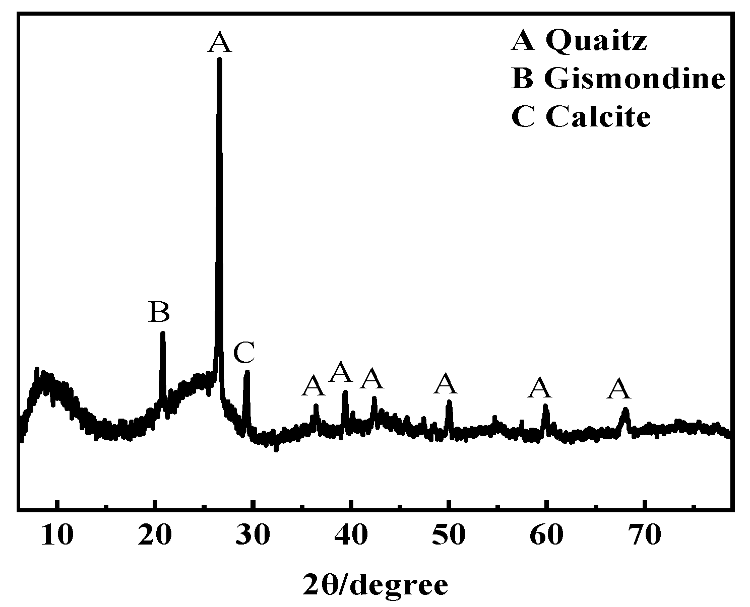
To determine the mineral types in the CGFS, XRD was used for physical phase analysis. As shown in Figure 1, the CGFS exhibits bulging peaks between 5° and 40°, indicating the presence of amorphous phases. Additionally, the bulging peaks at around 26° and 44° correspond to the crystal planes of graphite structures (002) and (100), respectively. This indicates that the residual carbon in the gasification slag was partially graphitized by high-temperature gasification. The peaks at 2θ = 20.16°, 26.40°, and 29.40° indicate the presence of crystalline phases in the fine slag, mainly quartz SiO2, plagioclase, and calcite.
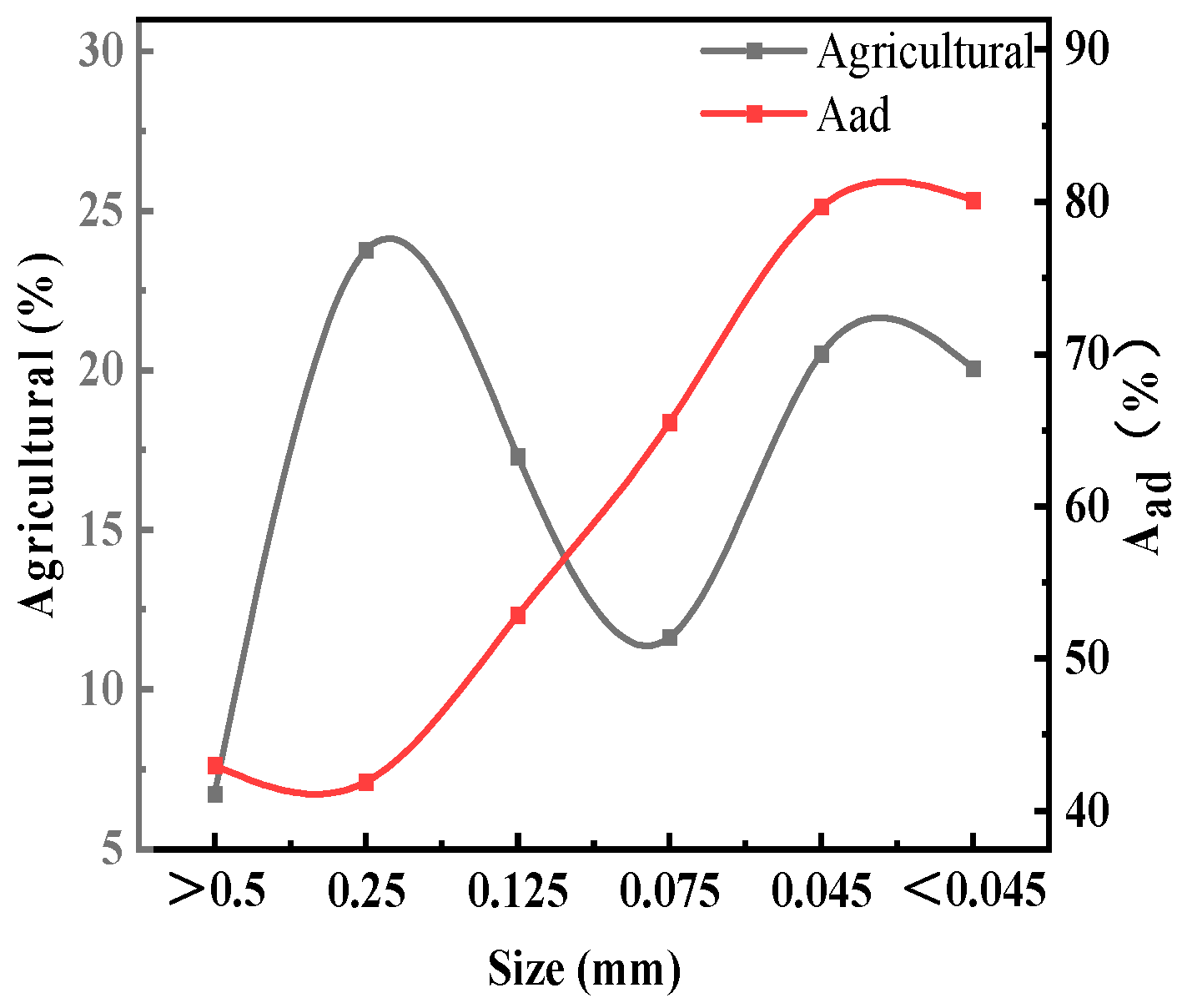
Figure 2 displays the particle size and ash distribution of the CGFS. The dominant particle size ranges are 0.074–0.045 mm and <0.045 mm, with a yield of approximately 20%. The ash contents of 79.69% and 80.12% are significantly higher than the original ore sample’s content of 60.51%. Furthermore, there is a higher content of material in the 0.5–0.125 mm particle size class, albeit with a relatively high ash content. Conversely, the >0.5 mm particle size class material has a lower yield of 6.73% and a higher ash content of 42.98%. To achieve optimal decarburisation, the <0.125 mm material was selected for further flotation decarburisation study.
2.2. Methods
Conventional flotation experiments were conducted using an XFDII inverter single-tank flotation machine (1.5 L, Nanchang Liyuan Mining and Metallurgical Equipment Co., Ltd., Nanchang, China). The flotation cell contained 60 g of CGFS fines and 1500 mL of water at a slurry concentration of 40 g/L. The impeller was rotated at 1800 rpm for 2 min with an airflow rate of 0.25 m3/min. Diesel and sec-octanol were added for contact times of 1 min and 30 s, respectively. The froth product was subsequently collected within 4.8 min after 30 s of aeration. In the surfactant pretreatment flotation test, a surfactant was added to the slurry during preparation at a concentration of 6 kg/t. All other procedures were identical to those used in conventional flotation. For ultrasound-assisted flotation, the slurry underwent pretreatment with ultrasound, and the remaining procedures were identical to those of conventional flotation. Finally, the flotation concentrates and tailings were washed, filtered, and dried at 75 °C for 12 h. The yield and ash content were measured by scorching in a muffle furnace at 950 °C for 2 h to evaluate the flotation efficiency based on the concentrate yield and ash content of each product.
The samples underwent cauterisation, pressing, and chemical composition analysis using an X-ray fluorescence spectrum analyser (Panalytical Axios FAST, Malvern panalytical, Almelo, The Netherland). The mineral composition of the synthetic samples was analysed using X-ray diffraction (D8 Advance, Bruker, Billerica, MA, USA) with a scanning range of 5–80°, step size of 0.02°, operating voltage of 40 kV, and current of 150 mA. A field emission scanning electron microscope (SU8220, Hitachi, Tokyo, Japan) was used to examine the microscopic morphology. The samples underwent vacuum degassing at 120 °C for 3 h. N2 adsorption and desorption were measured using a specific surface area and pore size analyser (V-Sord 2800MP Jinaipu Technology Co., Ltd., Beijing China). The specific surface area of the specimens in the range of P/P0 = 0.05–0.3 was calculated using the BET method. The desorption branch was analysed to determine the pore size distribution, which was combined with the analysis of the sample’s microstructure. The particle size of the samples was analysed using a laser particle sizer (Malvern ZS90, Malvern panalytical, Almelo, The Netherland) with distilled water as the dispersant and ultrasonication for 60 s. Structural analysis was conducted using a Fourier infrared spectral analyser (IRTracer-100, SHIMADZU, Kyoto, Japan) with a scanning range of 400 cm−1 to 4000 cm−1.
Surfactant adsorption was measured using an ultraviolet spectrophotometer (UV-3600, SHIMADZU, Kyoto, Japan). The three surfactants were prepared as a solution with a mass concentration of 0.01 g/mL for spare parts. A standard solution was also prepared, and a standard curve was measured. An appropriate amount of the solution was added to the slurry, which was left to be adsorbed for 12 h. The slurry was then centrifuged at low speed, and the concentration of surfactants in the centrifuged solution was measured using an ultraviolet spectrophotometer. The concentration of surfactant in the solution was determined by measuring its absorbance using a UV spectrophotometer. To calculate the amount of agent adsorbed on the surface of the sample, it is necessary to use the differential subtraction method, which can be calculated using the following formula:
W = (C0 − C1) × V/m
The amount of surfactant adsorbed on the surface of the sample (W) is measured in grams per gram. The concentration of surfactant in the solution before (C0) and after (C1) adsorption is measured in grams per litre. The volume of the adsorption solution (V) is measured in litres, and the mass of the sample (m) is measured in grams.
3. Results and Discussion
3.1. Effect of Ultrasonic Modification of CGFS on Flotation Decarbonisation
3.1.1. Discussion of Flotation Results
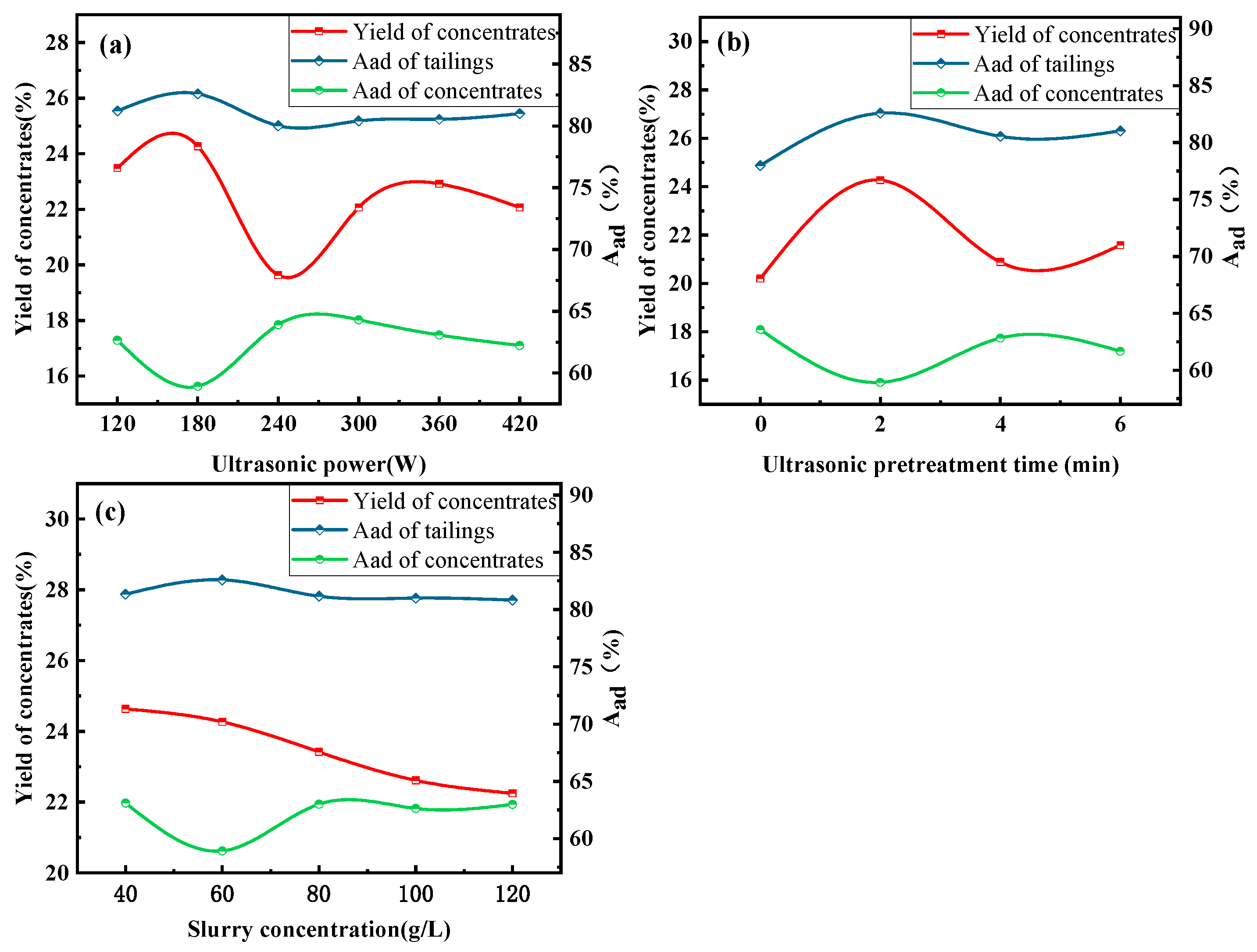
Figure 3 displays the flotation results of ultrasonically pretreated CGFS samples under varying conditions; with the increase in ultrasonic power, the concentrate yield initially increased and then decreased. The best flotation effect was observed at an ultrasonic power of 180 W, where the ash content of the concentrate is at its lowest, with a concentrate yield of 24.26% and tailing ash yield of 82.59%. Increasing the ultrasound time resulted in a decrease in concentrate yield, a decrease in tailings ash, and an increase in concentrate ash. This may be due to excessive ultrasound causing the breakdown of CGFS and worsening the flotation effect. The overall trend in concentrate yield decreased with increase in slurry concentration. When the slurry concentration was 60 g/L, the concentrate ash proportion was 58.92%, which was the lowest proportion, and the highest tailings ash content was 82.59%. In summary, ultrasonic pretreatment can significantly enhance the separation efficiency of residual carbon and inorganic minerals. The optimal settings are as follows: ultrasonic power = 180 W, time = 2 min, and slurry concentration = 60 g/L.
3.1.2. Particle Wettability Analysis
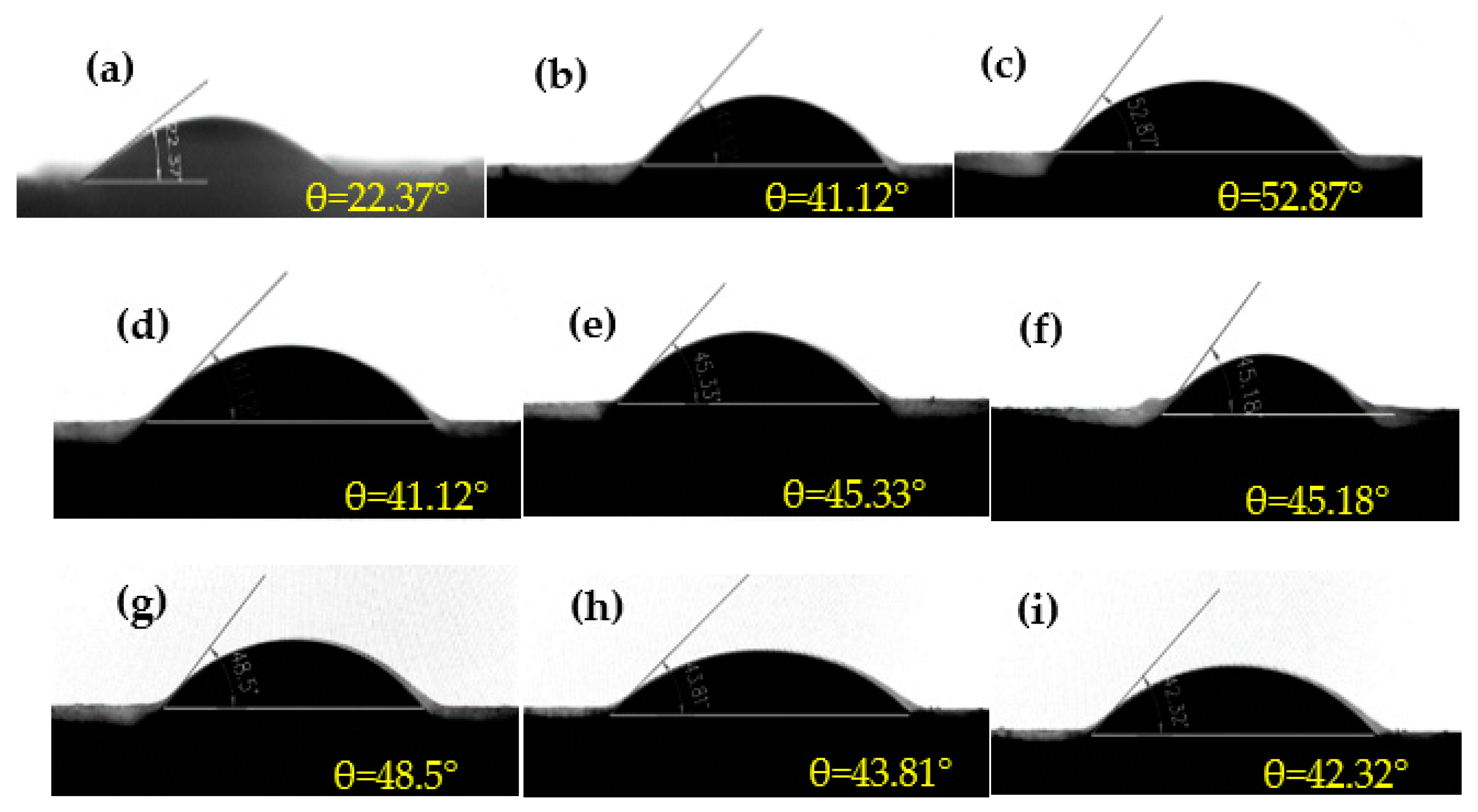
Ultrasonic pretreatment significantly affects the surface wettability of CGFS. High contact angle means stronger hydrophobicity and stronger floatability. The contact angles of different coal gasification fine slag samples are shown in Figure 4. The CGFS original sample exhibited a low contact angle of only 22.37°, indicating higher hydrophilicity. The hydrophobicity of the CGFS residue surface was significantly enhanced after ultrasonic pretreatment. Specifically, at an ultrasonic power of 420 W, the contact angle increased by 30.5°, and after 6 min of ultrasonication, the contact angle increased by 22.37°. With increase in ultrasonication power and time, the ultrasonication effect improved continuously. The cleaning effect of ultrasonic waves made the inorganic minerals on the surface of residual carbon flake off, sometimes destroying the oxidised layer on the surface and exposing a fresh hydrophobic surface. Increases in slurry concentration during ultrasonication will decrease the contact angle because of the limited concentration of slurry that can be processed by ultrasonic waves. The cavitation bubbles generated under the same ultrasonic conditions are limited and when the slurry concentration increases, some of the CGFS is not cleaned and is broken.
3.1.3. Micro-Morphological Analysis
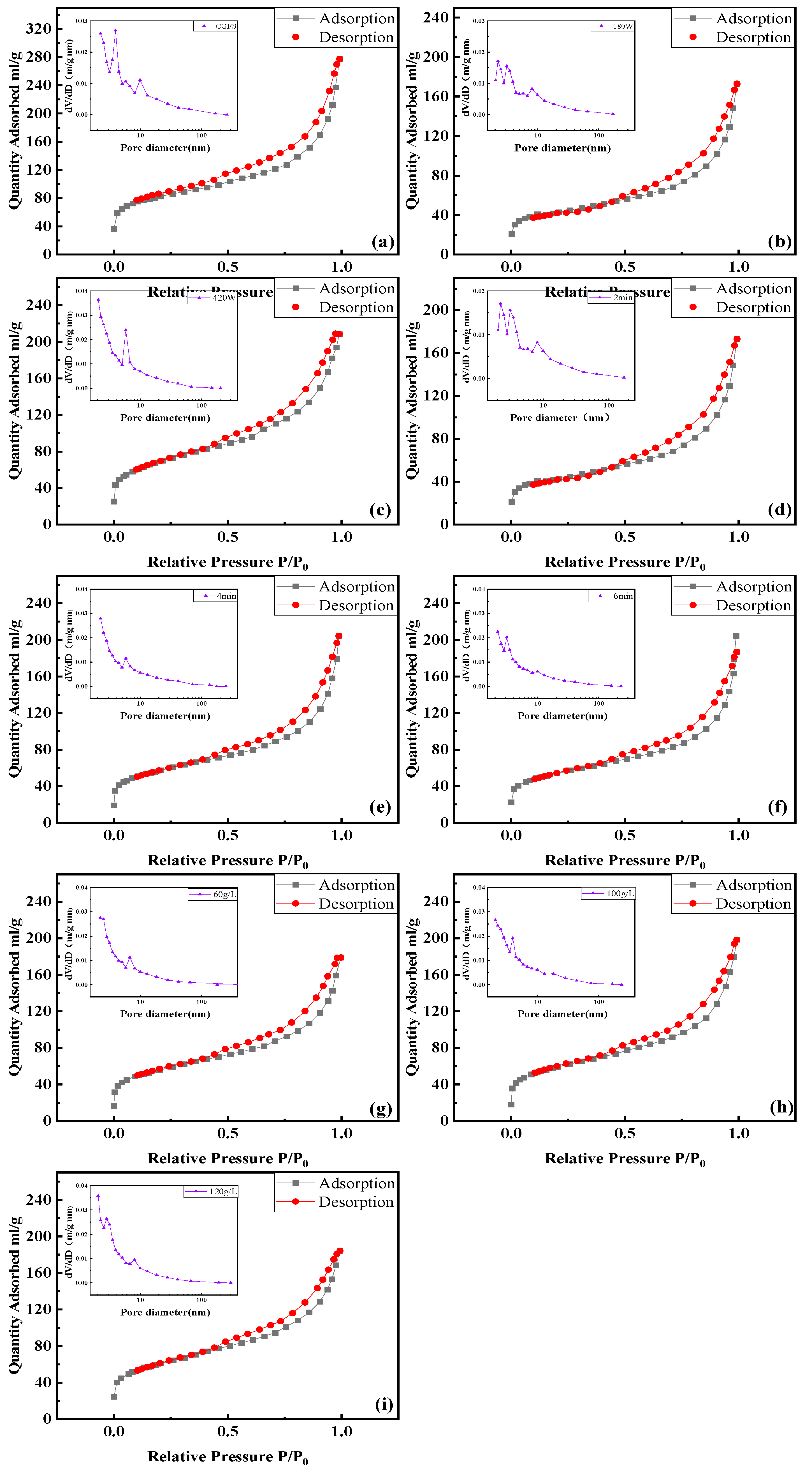
Figure 5 displays the N2 adsorption–desorption isotherms and pore size distribution curves of ultrasonically pretreated CGFS residue. The results indicate that ultrasonic treatment did not alter the adsorption curves, suggesting that the pore structure of the CGFS residue remained unchanged. When the ultrasonic power is increased to 180 W, the number of slightly larger pores increases. This suggests that ultrasonic waves have a cleaning effect on the residual carbon, causing the glass beads in the pores of the residual carbon to vibrate out. As a result, a large number of large pores are exposed and their number increases. When the ultrasonic power is too high, the large pores are destroyed, the stripping effect of ultrasonic waves is obvious, and the small pores increase. An overlong ultrasonication time creates ultrasonic excess. When the slurry concentration is too high, the ultrasonic effect is poor. The large pores in the residual carbon are embedded with ash particles, which causes the pore sizes to be small, so the content of small pores increases.
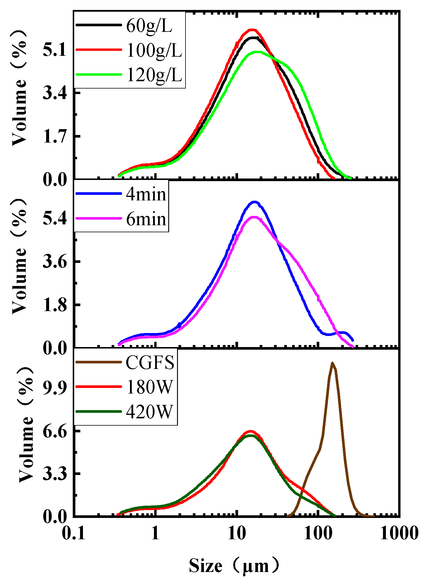
Figure 6 shows the effect of ultrasonication on the particle size distribution of CGFS residue. The particle size decreases after ultrasonic pretreatment. With increasing ultrasonication power, the change in particle size is subtle. However, it is still noticeable that larger particles decrease in size, while smaller particles increase in size. Additionally, with an increasing ultrasonication time, the sample’s main particle size range widens. When the slurry concentration decreases during ultrasonication, the size of the sample particles becomes small. This may be because the ultrasonic waves clean out the fine inorganic mineral particles in the pores of the CGFS. Additionally, the crushing effect of ultrasonic waves is also an important factor promoting a reduction in the particle size of the gasification fine residue. However, it is important to note that a high concentration of slurry can negatively affect the effectiveness of ultrasonic cleaning and crushing. The difference in particle size between ash and residual carbon is increased by ultrasonic pretreatment of CGFS, resulting in the effective release of ash during the flotation process.
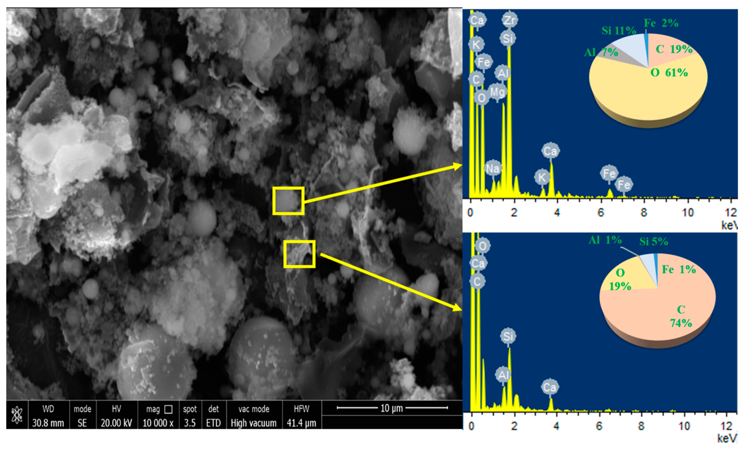
The morphology of CGFS was analysed using SEM (Figure 7). The surface energy spectrum analysis of the gasification fine slag reveals that the surface elements of the CGFS are mainly composed of C, O, Fe, Al, and Si, which is consistent with the XRD analysis. Upon spot scanning of the rough, flocculent, and spherical particles in the samples, it was revealed that the flocculants contained a high elemental C content of 74%. This indicated that the substance was flocculated residual carbon. The gasification residue contained residual carbon with a rough surface, was loose and porous, and was mostly in the form of lumps or flakes. The spherical particles contained only 19% carbon, which was residual carbon attached to the surface of inorganic minerals in the melt. The CGFS contained spherical glass beads with smooth surfaces. The microscopic morphology of the slag revealed that numerous inorganic minerals were enveloped and embedded in the voids of the residual carbon, which made flotation more challenging.
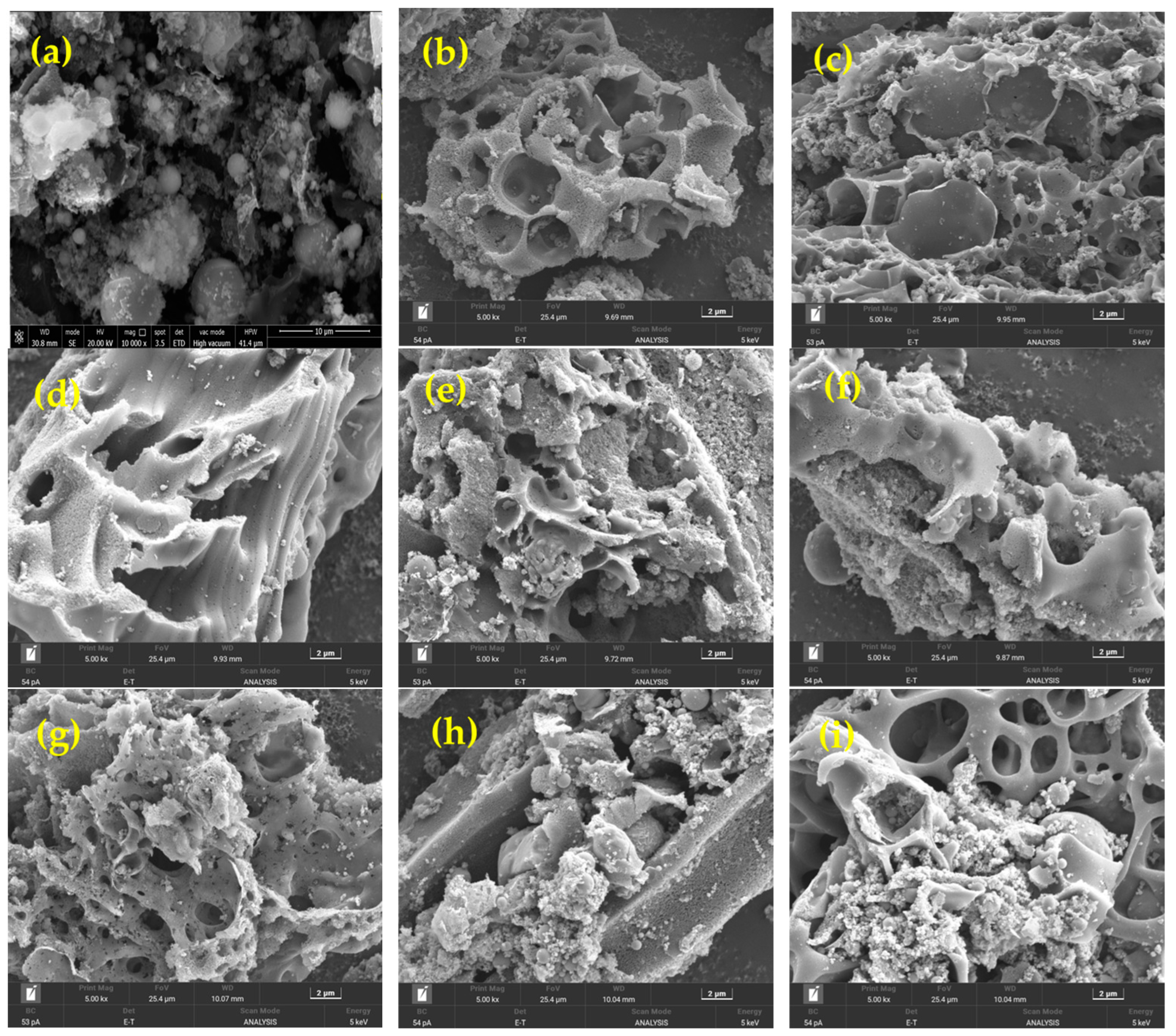
The microscopic morphology of CGFS after ultrasonic pretreatment is displayed in Figure 8. The use of ultrasound to treat the CGFS resulted in a significant reduction in ash particles in the pores. Additionally, a large number of fresh, smooth, and flat pores were exposed as new micropores appeared and the surface of residual carbon was fractured. Excessive ultrasonic power can destroy the macropores on the surface of residual carbon, resulting in smoother planes with fewer macropores. Similarly, the surface of residual carbon can be broken by prolonged ultrasonic exposure, leading to the formation of new micropores. It is important to carefully control the ultrasonic power and time to avoid these effects. As the slurry concentration increases, the effectiveness of ultrasonic cleaning decreases. Additionally, the number of ash particles in the macropores of the residual carbon surface layer noticeably increases. This is consistent with the BET and particle size analyses. In summary, ultrasound can have a good dissociation effect on CGFS residue, strip the inorganic minerals wrapped in the surface of the residual carbon particles and pores, make the carbon and ash separate to a greater extent, promote flotation, and improve the ash content of tailings.
3.1.4. Surface Structure Analysi
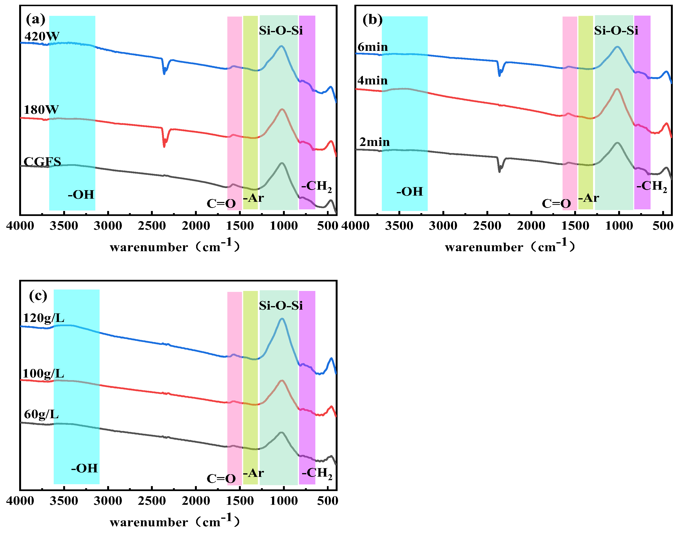
The FTIR spectrum of CGFS subjected to ultrasonic pretreatment is depicted in Figure 9. The peaks at approximately 750 cm−1 correspond to -CH2 methylene plane vibrations. Around 1029 cm−1, there are asymmetric vibrations in the silica-aluminate minerals (Si-O-Si, Si-O-Al), backbone vibrations of the benzene ring, C-O telescoping vibrations, and C-H deformation vibrations. At 1490 cm−1, there are backbone vibrations of the benzene ring, while at 1680 cm−1 and 1610 cm−1, there is a C=C stretching vibration of the aromatic ring and a carbon–oxygen double bond stretching vibration of the carboxyl group, respectively. The carboxyl group COOH exhibits an OH bond stretching vibration at 3200–2400 cm−1, while the hydroxyl group -OH shows absorption peaks at 3400–3700 cm−1, representing an H bond stretching vibration. The effective removal of the hydrophilic oxide layer on the surface of CGFS can be achieved through ultrasonic pretreatment, resulting in an enhanced concentrate yield. Figure 9 displays the infrared spectra of CGFS that underwent ultrasonic treatment. There are no discernible differences in the types of functional groups present under different conditions. Upon comparison with the original samples, it is evident that the peaks at C=O are significantly lower, the peaks at -CH2 are noticeably higher, and the peak intensities at Si-O-Si are reduced. Additionally, there is a peak variation between 800 and 1200 cm−1, which may be attributed to the synergistic effect of multiple functional groups.
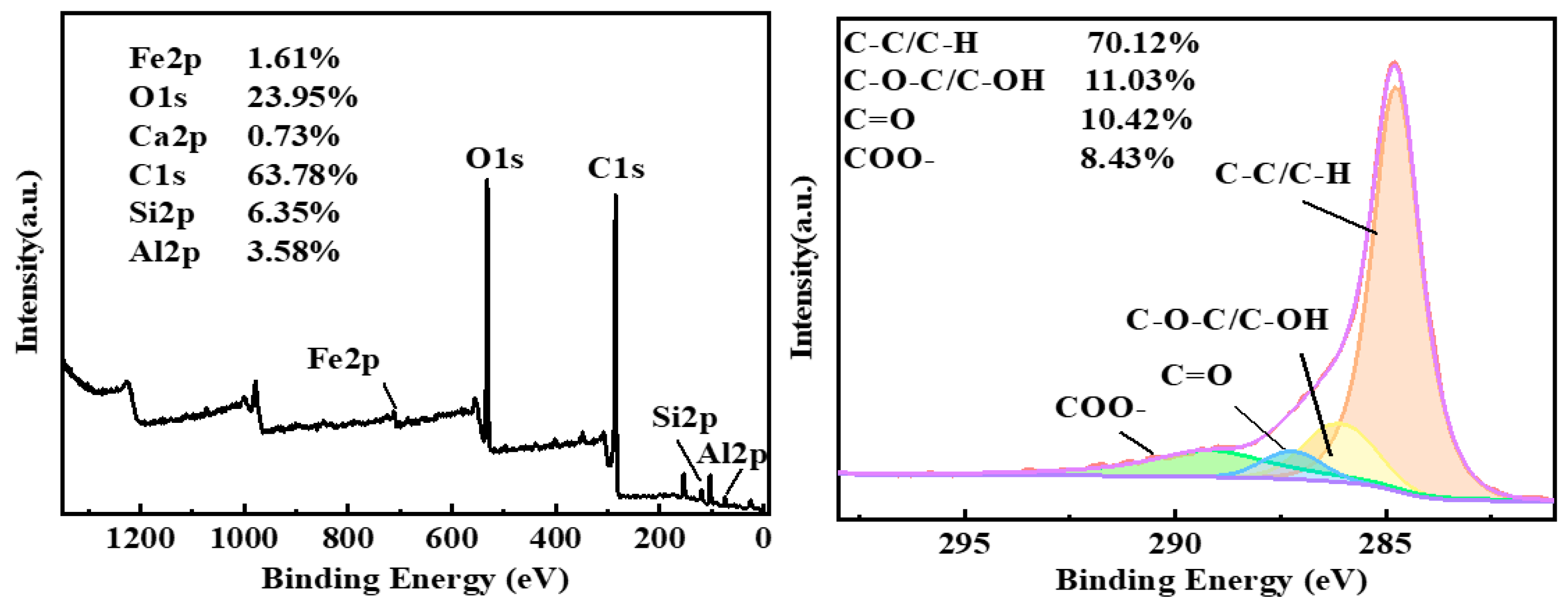
Full-spectrum and narrow-range scanning of C elements using XPS were employed to test the CGFS. The results of XPS broad scanning on the surface of the coal samples are presented in Figure 10. Quantitative analysis revealed that the surface of the coal samples contained 63.78% carbon, 23.95% oxygen, 6.35% silicon, 3.58% aluminium, 1.61% iron, and 0.73% calcium. Split-peak fitting of the C peak showed that the content of oxygen-containing functional groups on the surface of the slag samples was the highest, with 68.64% of C-C or C-H groups, 13.05% of C-O-C/C-OH groups, 13.13% of COO- groups, and 5.19% of C=O groups on the surface of the slag.
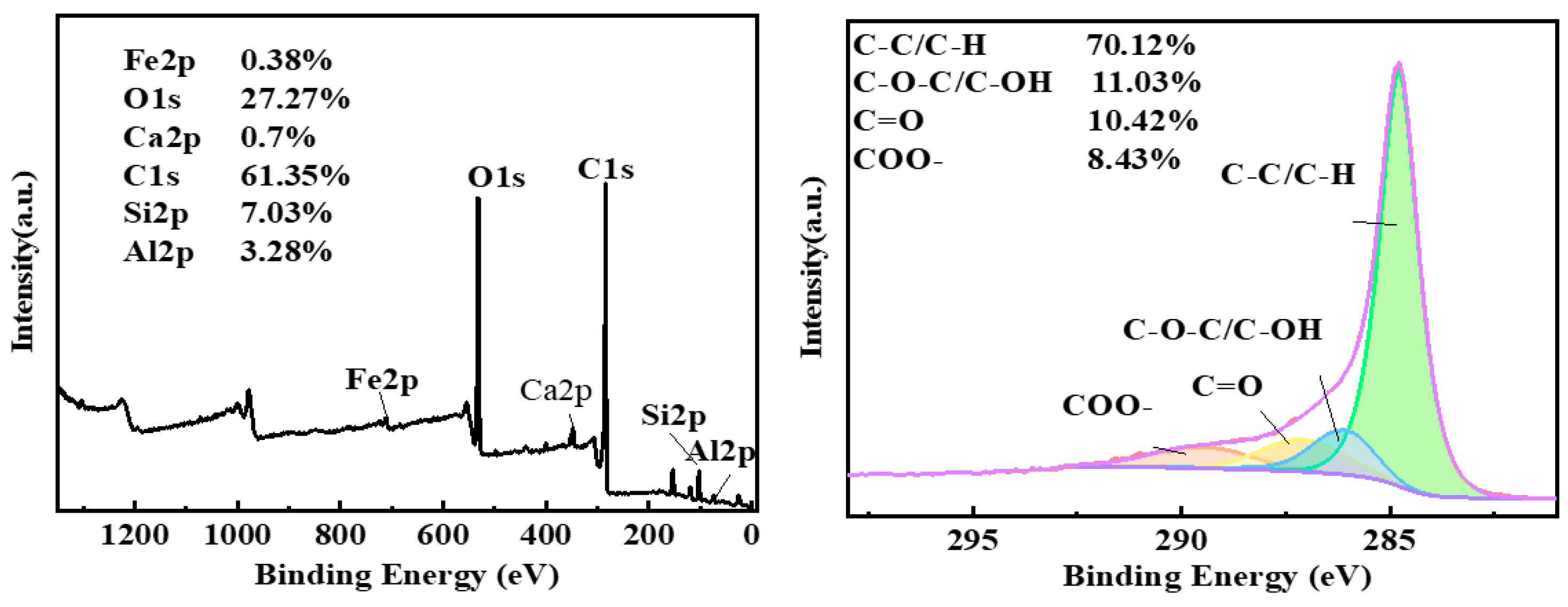
After subjecting the samples to optimal ultrasound pretreatment and analysing them using XPS, as shown Figure 11, it was observed that the C1s peak on the sample surface was significantly elevated compared to that of the original samples. However, the carbon content decreased by 2.43%, while the oxygen content increased by 3.32%. This change was attributed to the removal of oxides that were originally embedded in the pore structure of residual carbon due to the ultrasonic treatment. It is important to note that XPS mainly conducts elemental analysis on the surfaces of samples. A significant quantity of inorganic minerals was detected, such as elemental Si, the content of which increased by 0.68%. The split-peak fitting results of the C1s peak showed that the surface of the slag samples contained 70.12% C-C or C-H groups, an increase of 1.48% compared to the original samples. The C-O-C/C-OH groups decreased by 2.02%, and the COO- groups decreased by 4.7%. This indicates that ultrasound can reduce the content of oxygen-containing functional groups on the surface of residual carbon, significantly affecting the destruction of COO- groups and reducing the hydrophilicity of the CGFS surface.
3.2. Effect of Ultrasonic Pretreatment on Surfactant-Modified CGFS
3.2.1. Discussion of Flotation Results
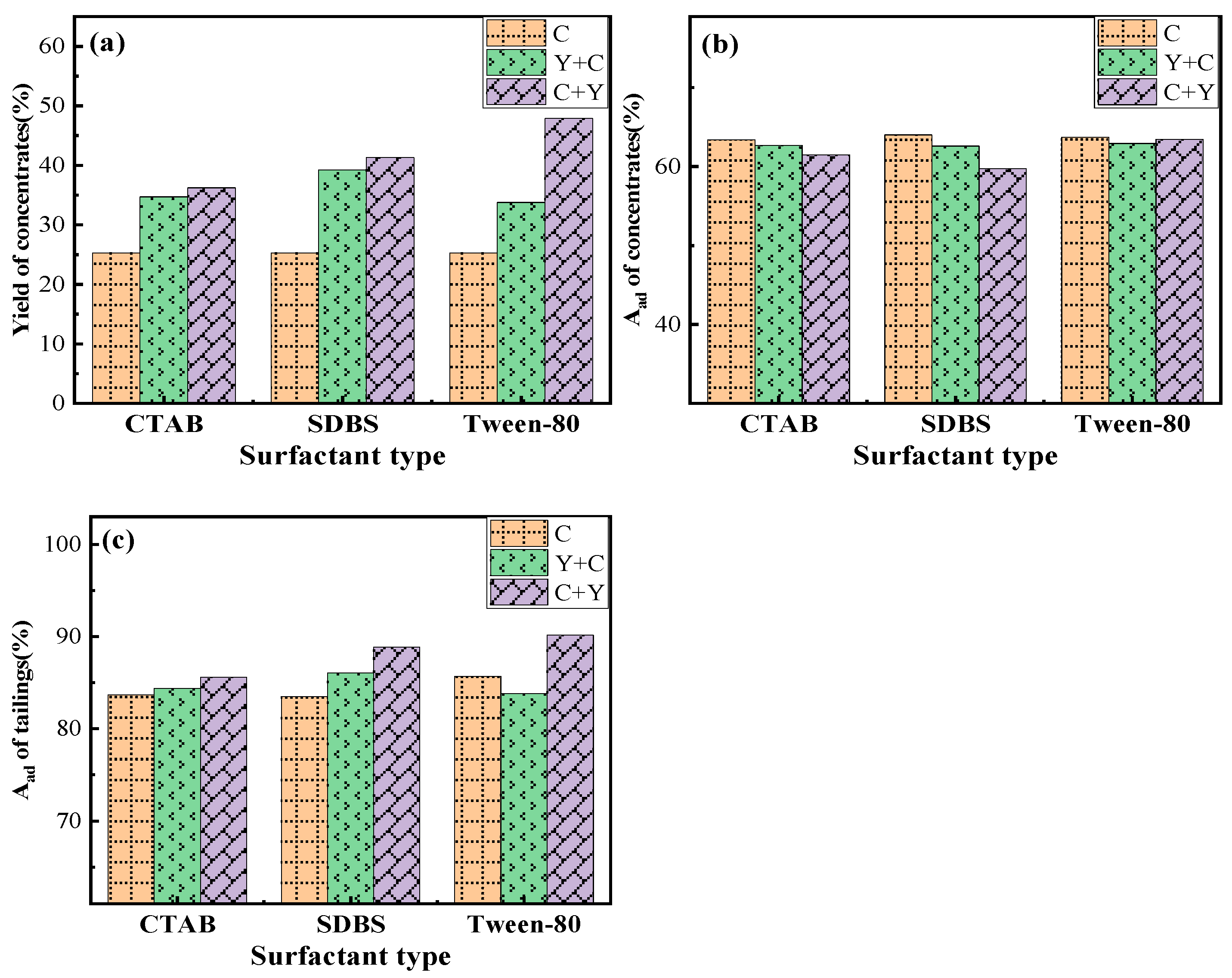
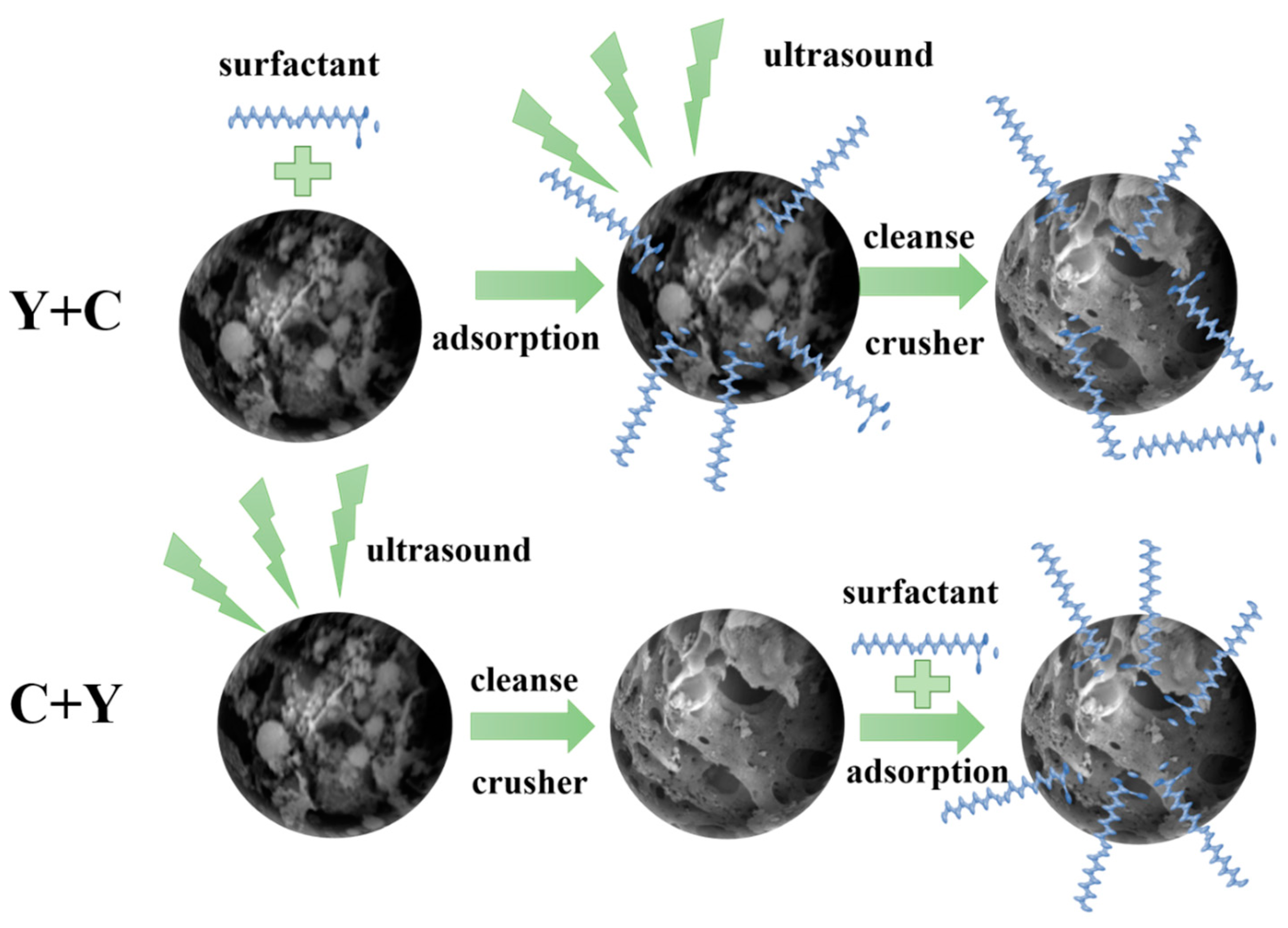
At a slurry concentration is 60 g/L, ultrasonication time of 2 min, and ultrasonication intensity of 180 W, various surfactants were added to investigate the combined effect of the ultrasonic field and surfactants. These include hexadecyl trimethyl ammonium Bromide (CTAB), sodium dodecyl benzene sulfonate (SDBS), and Tween-80. The flotation effect is presented in Figure 12. The combination of ultrasonication and surfactant has a synergistic effect, resulting in significant improvements in both yield and tailing ash. Specifically, the addition of Tween-80 had a particularly significant effect on yield, which increased to 47.9%, while the ash content of the tailings increased to 90.17%. Furthermore, variations in ultrasonication and surfactant treatments may impact the flotation of CGFS. This study compared two treatment methods: Method 1 involved simultaneous ultrasonication and surfactant pretreatment of slag samples (denoted Y + C), while Method 2 involved ultrasonic treatment of slag samples followed by surfactant treatment (denoted C + Y). The flotation effect of Y + C was generally better than that of C + Y. Additionally, the yield, flotation perfection index, and tailing ash were significantly improved. This may be attributed to the ultrasonic treatment cleaning the inorganic minerals on the surface of the residual carbon. The residual carbon was also crushed to reveal a fresh hydrophobic surface and reduce porosity. This allowed the surfactant to better attach to the residual carbon surface, making it easier to select.
3.2.2. Particle Wettability Analysis
The effect of ultrasound-assisted surfactant pretreatment on contact angle is shown in the Figure 13a. When ultrasonication was used with surfactant treatment, the CGFS contact angle was further increased. The contact angle increased by around 5–9° in Method Y + C, where the addition of CTAB had the best effect, causing an increase of 9.32°. Method C + Y, on the other hand, provided the maximum increase in contact angle of 58.72° when the samples were treated with SDBS agent. Ultrasonic synergistic surfactant treatment enhances the flotation of CGFS. The contact angle is significantly greater when surfactant is added after ultrasonication compared to ultrasonication, which is consistent with the flotation results. The effect of ultrasound-assisted surfactant pretreatment on Zeta potential is shown in the Figure 13b. The Zeta value of the slag sample was –30.38 mV, and the CGFS surface had a negative charge. After ultrasonic pretreatment, the absolute value of the Zeta potential decreased, indicating a reduction in electro-negativity. This suggests that ultrasonic pretreatment is effective in reducing the content of oxygen-containing functional groups on the surface of slag and in destroying large pores on the surface of residual carbon. Upon the addition of surfactant, a significant decrease in measured Zeta potential was observed, indicating the adsorption of surfactant onto the surface hydrophilic groups. This resulted in the outward orientation of the hydrophobic end, which enhanced the hydrophobicity of the residual carbon surface.
3.2.3. Adsorption Characterisation
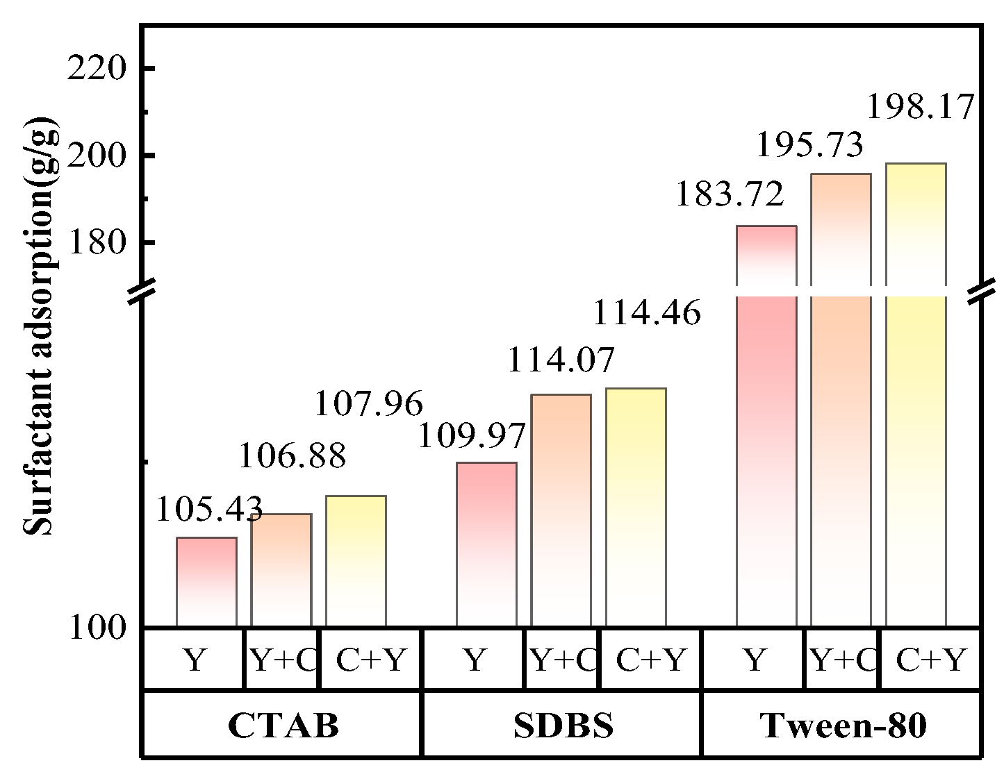
To confirm the reason for the improved flotation effect of Method C + Y and verify our previous conjecture, we measured the amounts of CGFS adsorption on different surfactants under different modes. Figure 14 shows that, in general, the non-ionic surfactant provides the highest adsorption amount. This is because of the lower adsorption selectivity of non-ionic surfactant, which allows it to be adsorbed on the surface of residual carbon as well as on the surface of inorganic minerals. Additionally, ultrasonic treatment may enhance the adsorption of surfactants by CGFS, resulting in an increase of up to 14.45 g/g. Comparing the adsorption amounts of Methods Y + C and C + Y, it is evident that the effect of the three agents is the same. When surfactants are pretreated with ultrasound together with the slurry, the amount of surfactant adsorption decreases, with a maximum reduction of 2.44g/g. This proves that sonication can desorb the agent that has been adsorbed onto the surface of CGFS. On the other hand, first sonicating the slurry and then adding an agent can increase the amount of surfactant adsorption. The adsorption between surfactant and CGFS is mainly dominated by electrostatic and intermolecular van der Waals forces. When the surfactant is added to adsorb with CGFS and then subjected to ultrasound, the ultrasound may cause desorption, stripping the surfactant from the residual carbon, resulting in a poorer flotation effect.
3.3. Mechanism Analysis and Flotation Process Optimisation
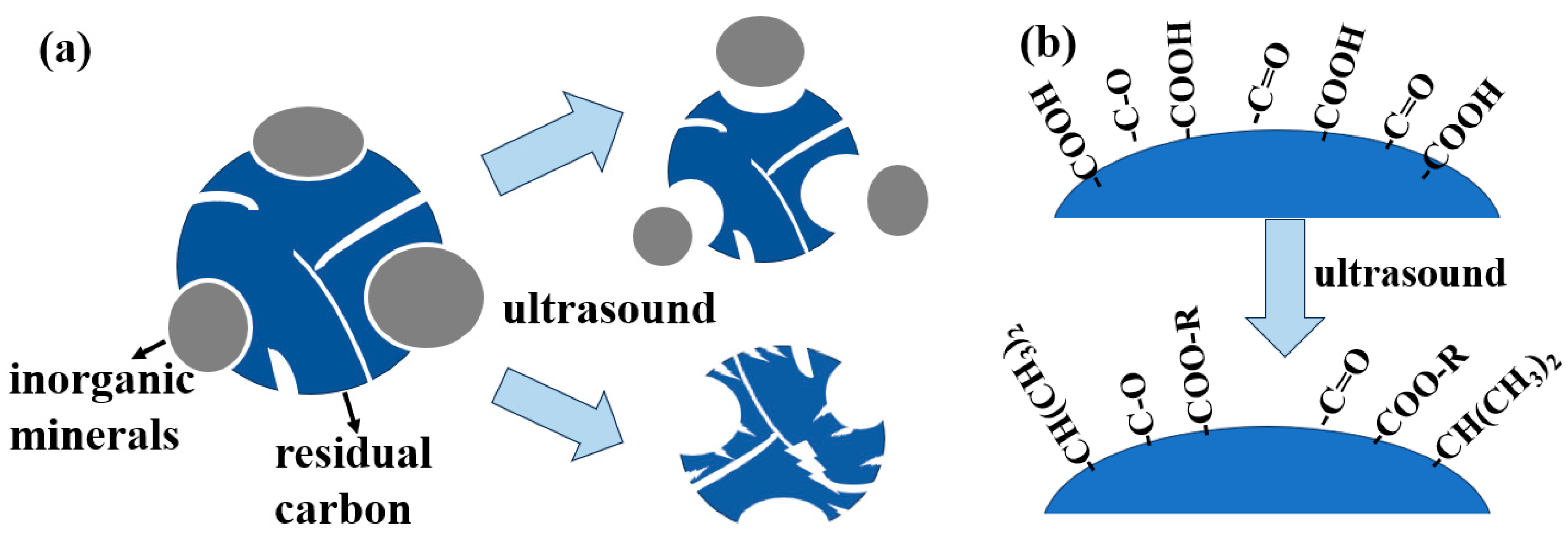
In CGFS, ultrasonication action is primarily related to mechanical and cavitation effects [26]. The implosion of cavitation bubbles generates high temperatures and pressures, resulting in micro-jets and strong shear forces that affect the microscopic morphology of CGFS. This mechanism illustrated in Figure 15a shows that this can remove inorganic minerals from pores, reduce the carryover of fine ash in the flotation process, and increase the number of fractures in the carbon particles, which improve connectivity [27]. Furthermore, ultrasound has the ability to decrease the amount of oxygen-containing functional groups presented on the surface of residual carbon. This is shown in Figure 15b, where the reaction equation for the elimination of carboxyl and carbonyl groups [28] is provided:
R-COOH + R′ → R-COO-R′ + H2O
R-C(CH3)2-COOH → R-CH(CH3)2 + CO2
R-C′=O → R′ + CO
In summary, the combination of ultrasound and surfactant can enhance the CGFS flotation effect. The mechanism is illustrated in Figure 16. The surfactant is adsorbed onto the surface of slag and interacts with oxygen-containing functional groups through van der Waals forces, electrostatic potential energy, and hydrogen bonding to expose the hydrophobic ends, which improve the flotation effect. Ultrasonic cleaning and crushing can enhance the residual hydrophobicity of carbon and reduce the size of gasification slag particles. This is accomplished by the transmission of high-speed shock waves or micro-jets, which remove the residual carbon surface and inorganic minerals in the pore space, revealing fresh hydrophobic surfaces. The smaller particle size of the gasification slag facilitates its combination with ore slurry surfaces, resulting in a concentrate through flotation froth. The order in which ultrasonic and surfactant pretreatments are applied can significantly affect the flotation effect. If the surfactant is adsorbed on the CGFS surface before ultrasonication, the shock waves generated by ultrasonic cavitation can destroy the hydrogen bonds between the agent and residual carbon [29], causing a desorption effect and greatly reducing flotation. However, ultrasonic pretreatment can expose more active sites on the CGFS for the surfactant to attach to, thereby improving flotation.
Based on the flotation results, the optimal flotation process is presented in Figure 1. Firstly, ultrasonic pretreatment is conducted on the CGFS, followed by the addition of surfactants for chemical modification. This changes the structure and surface properties of the CGFS. Finally, the conventional flotation process is carried out to enhance the flotation of CGFS.
4. Discussion
To enhance the comprehensive utilisation efficiency of CGFS, this study examined the impact of ultrasonic treatment power and time, as well as slurry concentration, on the flotation performance of CGFS during the ultrasonic pretreatment process. Based on these findings, CGFS was pretreated with surfactant, and the effects of ultrasonic and surfactant pretreatment were compared in different orders. The results provide a reference for enhancing the CGFS flotation process. The main conclusions are as follows:
(1) Ultrasonic pretreatment can significantly improve the separation efficiency of residual carbon and inorganic minerals. The optimal settings are as follows: ultrasonic power = 180 W, time = 2 min, and slurry concentration = 60 kg/L. This provided the maximum fine coal yield and ash content, a concentrate yield of 24.26%, concentrate ash content of 58.92%, and tailings ash content of 82.59%.
(2) Ultrasonic pretreatment can clean the ash particles in the pores of CGFS, destroy the large pores, create new micropores, expose a large number of fresh smooth plane pores, reduce the particle size of CGFS, and even remove the surface oxidation film, exposing fresh hydrophobic surfaces. Ultrasonic pretreatment decreased the content of hydrophilic groups from 31.64% to 29.88%, of which the COO- groups decreased from 13.13% to 8.43%, which is a significant effect.
(3) Among the various treatment methods investigated, ultrasonic treatment was found to be effective in desorbing the adsorbed agent on the surface of CGFS due to the predominance of electrostatic force, intermolecular van der Waals force, and hydrogen bonding in the adsorption process. Ultrasonic treatment should be employed to enhance the hydrophobicity of the surface of CGFS and increase the number of surface-active sites. Subsequently, adding a surfactant can further increase the adsorption amount of the surface-active agent, leading to a more effective treatment of CGFS. Which result in tailings with an ash content of up to 90.17%.
Author Contributions
Conceptualization, Y.J., Z.Y. and X.H.; Formal analysis, Y.J., K.W. and Z.Z.; Funding acquisition, Z.Y.; Investigation, Y.J. and Z.Y.; Methodology, Y.J., Z.Y., X.H., C.F. and W.T.; Software, Y.J.; Supervision, Z.Y.; Validation, Z.Y.; Writing—original draft, Y.J. All authors have read and agreed to the published version of the manuscript.
Funding
This research was funded by Inner Mongolia Autonomous Region Science and Technology Plan Foundation, grant numbers 2020GG0287, 2020GG0257, 2022YFHH0050 and 2023SYFHH0289, Inner Mongolia Natural Science Foundation Project, grant numbers 2023LHMS05010, Hohhot Science and Technology Plan Project, grant numbers 2023-Society-11, Inner Mongolia University of Technology Educational Reform Foundation, grant number 2022109, the “14th Five Year Plan” for Educational Science Research in Inner Mongolia Autonomous Region, grant numbers NGJGH2022093, and 2023 Graduate Education and Teaching Reform Project in Inner Mongolia Autonomous Region, grant numbers JGCG2023086, 2024 Inner Mongolia Autonomous Region Directly Affiliated Universities Basic Research Business Fund Project, grant numbers JY20240027.
Data Availability Statement
The data presented in this study are available on request from the corresponding author. When the project was carried out, there was no obligation to make the data publicly available.
Conflicts of Interest
The authors declare no conflicts of interest.
References
- Wu, L.B.; Song, M.Y.; Xie, X.; Ma, Y.J. A Review on Resource Utilization of Coal Gasification Slag as Building Materials in China. Sci. Technol. Eng. 2021, 21, 6565–6574. (In Chinese) [Google Scholar]
- Ren, P.L. Experimental Study on Deashing of Fine Slag from Coalgasification by Grinding Flotation. Master’s Thesis, Xi’an University of Science and Technology, Xi’an, China, 2021; p. 000104. (In Chinese). [Google Scholar]
- Peng, Y.L.; Mao, Y.Q.; Xia, W.C.; Li, Y. Ultrasonic flotation cleaning of high-ash lignite and its mechanism. Fuel 2018, 220, 558–566. [Google Scholar] [CrossRef]
- Cilek, E.C.; Ozgen, S. Effect of ultrasound on separation selectivity and efficiency of flotation. Miner. Eng. 2009, 22, 1209–1217. [Google Scholar] [CrossRef]
- Jin, L.Z.; Wang, W.D.; Tu, Y.A.; Zhang, K.; Lv, Z. Effect of ultrasonic standing waves on flotation bubbles. Ultrason. Sonochem. 2021, 73, 105459. [Google Scholar] [CrossRef]
- Cheng, G.; Zhang, M.N.; Lu, Y.; Zhang, H.J.; Lau, E.V. New insights for improving low-rank coal flotation performance via emulsified waste fried oil collector. Fuel 2024, 357, 129925. [Google Scholar] [CrossRef]
- Ozkan, S.G. Further Investigations on Simultaneous Ultrasonic Coal Flotation. Minerals 2017, 7, 177. [Google Scholar] [CrossRef]
- Toraman, O.Y. Experimental investigations of preparation of calcite particles by ultrasonic treatment. Physicochem. Probl. Miner. Process. 2017, 53, 859–868. [Google Scholar] [CrossRef]
- Sahinoglu, E.; Uslu, T. Effects of various parameters on ultrasonic comminution of coal in water media. Fuel Process. Technol. 2015, 137, 48–54. [Google Scholar] [CrossRef]
- Shi, Q.M.; Qin, Y.; Zhou, B.Y.; Wang, X. Porosity changes in bituminous and anthracite coal with ultrasonic treatment. Fuel 2019, 255, 115739. [Google Scholar] [CrossRef]
- Chen, Y.R.; Chelgani, S.C.; Bu, X.N.; Xie, G.Y. Effect of the ultrasonic standing wave frequency on the attractive mineralization for fine coal particle flotation. Ultrason. Sonochem. 2021, 77, 105682. [Google Scholar] [CrossRef]
- Liu, X.Y.; Liu, S.Y.; Fan, M.Q.; Zhang, L. Decrease of hydrophilicity of lignite using CTAB: Effects of adsorption differences of surfactant onto mineral composition and functional groups. Fuel 2017, 197, 474–481. [Google Scholar] [CrossRef]
- Xu, M.; Li, C.W.; Wang, Y.T.; Zhang, H.J. Investigation on mechanism of intensifying coal fly ash froth flotation by pretreatment of non-ionic surfactant. Fuel 2019, 254, 115601. [Google Scholar] [CrossRef]
- Gao, F.; Dong, L.P.; Xue, Z.H.; Cai, S.J.; Fan, M.Q.; Hao, B.; Fan, P.P.; Bao, W.R.; Wang, J. Dodecylamine enhanced coal gasification fine slag flotation and its molecular dynamics simulation. Miner. Eng. 2023, 203, 108322. [Google Scholar] [CrossRef]
- Jarrahian, K.; Seiedi, O.; Sheykhan, M.; Sefti, M.V.; Ayatollahi, S. Wettability alteration of carbonate rocks by surfactants: A mechanistic study. Colloids Surf. A Physicochem. Eng. Asp. 2012, 410, 1–10. [Google Scholar] [CrossRef]
- Wen, P.C.; Ma, X.M.; Fan, Y.P.; Dong, X.S.; Chen, R.X. Study on the mechanism of anionic composite surfactant pretreatment to promote flotation of clay-rich coal slurry: Interfacial interaction. Colloids Surf. A Physicochem. Eng. Asp. 2024, 683, 133058. [Google Scholar] [CrossRef]
- Cheng, G.; Zhang, M.N.; Zhang, Y.H.; Lin, B.; Zhan, H.J.; Zhang, H.J. A novel renewable collector from waste fried oil and its application in coal combustion residuals decarbonization. Fuel 2022, 323, 124388. [Google Scholar] [CrossRef]
- Zhao, Z.F.; Li, Y.Z.; Zhang, Z.J. Effect of surfactant on the attachment between coal particles and bubbles: An experimental and molecular dynamics simulation study. Fuel 2023, 337, 127272. [Google Scholar] [CrossRef]
- Li, R.S.; Xie, Z.J.; Zhou, Y.; Wang, W.L.; Gui, X.H. Thin liquid film drainage mechanism for bubble—Particle attachment interactions in the low-rank coal flotation in the presence of salt and surfactants. J. Mol. Liq. 2024, 398, 124236. [Google Scholar] [CrossRef]
- Xia, Y.C.; Zhang, R.; Xing, Y.W.; Gui, X.H. Improving the adsorption of oily collector on the surface of low-rank coal during flotation using a cationic surfactant: An experimental and molecular dynamics simulation study. Fuel 2019, 235, 687–695. [Google Scholar] [CrossRef]
- Xu, F.; Wang, S.W.; Kong, R.J.; Wang, C.Y. Synergistic effects of dodecane-castor oil acid mixture on the flotation responses of low-rank coal: A combined simulation and experimental study. Int. J. Min. Sci. Technol. 2023, 33, 649–658. [Google Scholar] [CrossRef]
- Chen, S.J.; Wang, S.W.; Li, L.L.; Qu, J.; Tao, X.; He, H. Exploration on the mechanism of enhancing low-rank coal flotation with cationic surfactant in the presence of oily collector. Fuel 2018, 227, 190–198. [Google Scholar] [CrossRef]
- Zhang, M.N.; Cheng, G.; Lu, Y.; Cao, Y.J.; Lau, E.V. Preparation of long-flame coal flotation collector from waste cooking oil. Miner. Eng. 2023, 202, 108296. [Google Scholar] [CrossRef]
- Wen, B.F.; Xia, W.H.; Sokolovic, J.M. Recent advances in effective collectors for enhancing the flotation of low rank/oxidized coals. Powder Technol. 2017, 319, 1–11. [Google Scholar] [CrossRef]
- He, J.F.; Liu, C.G.; Yao, Y.K. Flotation intensification of the coal slime using a new compound collector and the interaction mechanism between the reagent and coal surface. Powder Technol. 2018, 325, 333–339. [Google Scholar] [CrossRef]
- Luo, X.M.; Gong, H.Y.; He, Z.L.; Zhang, P.; He, L.M. Recent advances in applications of power ultrasound for petroleum industry. Ultrason. Sonochem. 2021, 70, 105337. [Google Scholar] [CrossRef] [PubMed]
- Liu, P.; Liu, A.; Zhong, F.X.; Jiang, Y.D.; Li, J.J. Pore/fracture structure and gas permeability alterations induced by ultrasound treatment in coal and its application to enhanced coalbed methane recovery. J. Petrol. Sci. Eng. 2021, 205, 108862. [Google Scholar] [CrossRef]
- Wang, H.H.; Dlugogorski, B.Z.; Kennedy, E.M. Thermal decomposition of solid oxygenated complexes formed by coal oxidation at low temperatures. Fuel 2002, 81, 1913–1923. [Google Scholar] [CrossRef]
- Luo, X.M.; Gong, H.Y.; He, Z.L.; Zhang, P.; He, L. Research on mechanism and characteristics of oil recovery from oily sludge in ultrasonic fields. J. Hazard. Mater. 2020, 399, 123137. [Google Scholar] [CrossRef]
Figure 1.
XRD spectrum of CGFS.

Figure 2.
Particle size and ash distribution of CGFS.

Figure 3.
Results of flotation experiments with different ultrasonic treatments of CGFS: (a) for different ultrasonic power treatments; (b) for different ultrasonic time treatments; (c) for different slurry concentrations.
Figure 3.
Results of flotation experiments with different ultrasonic treatments of CGFS: (a) for different ultrasonic power treatments; (b) for different ultrasonic time treatments; (c) for different slurry concentrations.

Figure 4.
Effect of different ultrasonic treatments on the contact angle of CGFS. (a) Original sample. Different ultrasonic powers: (b) 180 W, (c) 420 W. Different ultrasound times: (d) 2 min, (e) 4 min, (f) 6 min. Different slurry concentrations: (g) 60 g/L, (h) 100 g/L, (i) 120 g/L.
Figure 4.
Effect of different ultrasonic treatments on the contact angle of CGFS. (a) Original sample. Different ultrasonic powers: (b) 180 W, (c) 420 W. Different ultrasound times: (d) 2 min, (e) 4 min, (f) 6 min. Different slurry concentrations: (g) 60 g/L, (h) 100 g/L, (i) 120 g/L.

Figure 5.
N2 adsorption–desorption isotherms and pore size distribution profiles of ultrasonically pretreated CGFS. (a) Original sample. Different ultrasonic powers: (b) 180 W, (c) 420 W. Different ultrasound times: (d) 2 min, (e) 4 min, (f) 6 min. Different slurry concentrations: (g) 60 g/L, (h) 100 g/L, (i) 120 g/L.

Figure 6.
The particle size distribution curve of ultrasonically pretreated CGFS.

Figure 7.
SEM of CGFS after crushing.

Figure 8.
Microscopic morphology of ultrasonically pretreated CGFS. (a) Original sample. Different ultrasonic powers: (b) 180 W, (c) 420 W. Different ultrasound times: (d) 2 min, (e) 4 min, (f) 6 min. Different slurry concentrations: (g) 60 g/L, (h) 100 g/L, (i) 120 g/L.
Figure 8.
Microscopic morphology of ultrasonically pretreated CGFS. (a) Original sample. Different ultrasonic powers: (b) 180 W, (c) 420 W. Different ultrasound times: (d) 2 min, (e) 4 min, (f) 6 min. Different slurry concentrations: (g) 60 g/L, (h) 100 g/L, (i) 120 g/L.

Figure 9.
FTIR of ultrasonically pretreated CGFS: (a) for different ultrasonic power treatments; (b) for different ultrasonic time treatments; (c) for different slurry concentrations.
Figure 9.
FTIR of ultrasonically pretreated CGFS: (a) for different ultrasonic power treatments; (b) for different ultrasonic time treatments; (c) for different slurry concentrations.

Figure 10.
CGFS XPS spectrum and c-spectrum fitted to the peaks.

Figure 11.
XPS full spectrum and c-spectrum split-peak fitting of CGFS under optimal ultrasonic conditions.
Figure 11.
XPS full spectrum and c-spectrum split-peak fitting of CGFS under optimal ultrasonic conditions.

Figure 12.
Flotation results of the synergistic action of ultrasound and different surfactants. (a) Yield of concentrates. (b) Aad of concentrates. (c) Aad of tailings.
Figure 12.
Flotation results of the synergistic action of ultrasound and different surfactants. (a) Yield of concentrates. (b) Aad of concentrates. (c) Aad of tailings.

Figure 13.
Effect of ultrasonic co-surfactant pretreatment on contact angle (a) and Zeta potential (b) of CGFS in different ways.
Figure 13.
Effect of ultrasonic co-surfactant pretreatment on contact angle (a) and Zeta potential (b) of CGFS in different ways.

Figure 14.
Effect of ultrasonic co-surfactant pretreatment on adsorption of CGFS residue in different ways.
Figure 14.
Effect of ultrasonic co-surfactant pretreatment on adsorption of CGFS residue in different ways.

Figure 15.
Mechanism of ultrasonic pretreatment of coal gasification fines. (a) Mechanism of ultrasonic treatment on the surface morphology of CGFS. (b) Mechanism of ultrasonic treatment on oxygen-containing functional groups on the surface of CGFS.
Figure 15.
Mechanism of ultrasonic pretreatment of coal gasification fines. (a) Mechanism of ultrasonic treatment on the surface morphology of CGFS. (b) Mechanism of ultrasonic treatment on oxygen-containing functional groups on the surface of CGFS.

Figure 16.
Mechanism of ultrasonic and surfactant synergistic pretreatment of coal gasification fine slag.
Figure 16.
Mechanism of ultrasonic and surfactant synergistic pretreatment of coal gasification fine slag.


Table 1.
Industrial analysis, elemental analysis, and calorific value of CGFS.
| Proximate Analysis (wt%, ad) | Elemental Analysis (wdaf/%) | Calorific Value (KJ/kg) | |||||||
|---|---|---|---|---|---|---|---|---|---|
| M | A | V | FC | C | H | O | N | S | Qnet,V,Mad |
| 64.48 | 22.50 | 1.06 | 11.96 | 28.29 | 0.447 | 5.025 | 0.24 | 0.293 | 11,067.72 |
Table 2.
Chemical composition of CGFS.
| Chemical Composition | SiO2 | CaO | Al2O3 | Fe2O3 | Na2O | MgO | Other |
|---|---|---|---|---|---|---|---|
| Percentage/% | 47.0 | 14.4 | 15.6 | 12.8 | 2.16 | 1.79 | 6.25 |
Disclaimer/Publisher’s Note: The statements, opinions and data contained in all publications are solely those of the individual author(s) and contributor(s) and not of MDPI and/or the editor(s). MDPI and/or the editor(s) disclaim responsibility for any injury to people or property resulting from any ideas, methods, instructions or products referred to in the content. |
© 2024 by the authors. Licensee MDPI, Basel, Switzerland. This article is an open access article distributed under the terms and conditions of the Creative Commons Attribution (CC BY) license (https://creativecommons.org/licenses/by/4.0/).
Share and Cite
MDPI and ACS Style
Jiao, Y.; Yang, Z.; Han, X.; Wang, K.; Fang, C.; Zhao, Z.; Tang, W. Ultrasonication Improves the Flotation of Coal Gasification Fine Slag Residue. Minerals 2024, 14, 363. https://doi.org/10.3390/min14040363
AMA Style
Jiao Y, Yang Z, Han X, Wang K, Fang C, Zhao Z, Tang W. Ultrasonication Improves the Flotation of Coal Gasification Fine Slag Residue. Minerals. 2024; 14(4):363. https://doi.org/10.3390/min14040363
Chicago/Turabian StyleJiao, Yang, Zhijie Yang, Xing Han, Kaiyue Wang, Chenyang Fang, Zhiming Zhao, and Wenhao Tang. 2024. "Ultrasonication Improves the Flotation of Coal Gasification Fine Slag Residue" Minerals 14, no. 4: 363. https://doi.org/10.3390/min14040363
Note that from the first issue of 2016, this journal uses article numbers instead of page numbers. See further details here.