
A Systematic Approach for Energy-Efficient Design of Rolling Bearing Cages
by
 , , and
Anatoliy Gaydamaka
1,
Volodymyr Klitnoi
1 ,
,
Sergey Dobrotvorskiy
2,
Yevheniia Basova
2,
Demétrio Matos
3 and
and
José Machado
4,*
1
Department of Mechanical Engineering Machine Components and Hydropneumatic Systems, National Technical University “Kharkiv Polytechnic Institute”, 2, Kyrpychova St., 61002 Kharkiv, Ukraine
2
Department of Mechanical Engineering Technology and Metal-Cutting Machines, National Technical University “Kharkiv Polytechnic Institute”, 2, Kyrpychova St., 61002 Kharkiv, Ukraine
3
School of Design, Polytechnic Institute of Cávado and Ave, Campus of IPCA, Vila Frescaínha, S. Martinho, 4750-810 Barcelos, Portugal
4
MEtRICs Research Center, Campus of Azurém, University of Minho, 4800-058 Guimarães, Portugal
*
Author to whom correspondence should be addressed.
Appl. Sci. 2023, 13(2), 1144; https://doi.org/10.3390/app13021144
Submission received: 13 December 2022
/
Revised: 8 January 2023
/
Accepted: 10 January 2023
/
Published: 14 January 2023
(This article belongs to the Special Issue Development, Reliability, Maintenance and Control of Cyber-Physical Systems)
Abstract
:Featured Application
This study proposes a heat generation model for selecting an energy-efficient design for a rolling bearing cage.
Abstract
Several aspects must be considered in the design of rolling bearing cages. One of the most important considerations relates to studying and developing a stationary approach for solving problems of heat and mass transfer during convection. In this context, this paper proposes, among other achievements, the development and validation of a model of heat generation that is used, as the basis for an energy-efficient cage design in the context of the roller bearings of axle boxes for rail transport. The forces of interaction of the cage with the bearing parts are determined. The energy-efficient design of the cage is performed with modified friction surfaces in the form of convex contours of the pockets and micro-hollows on the surfaces of the pockets and support rings. On the basis of a flat model, of the interaction between the cage and the bearing parts, the pressure forces on the driving and driven rolling elements in the zone of radial loading are determined. The frictional moment of the bearing has been determined based on the integral design of the cage without taking into account lubrication during the interaction of the cage with the jumpers and with the sides of the basing ring. The calculation of the temperature gradient with standard and improved designs of bearing cages has been performed while taking air blowing into account; results showed a decrease in the average level and growth rate of the bearings’ temperature gradient with an energy-efficient cage design. Based on the obtained results, and on the developed heat generation model, a systematic approach for energy-efficient design of rolling bearing cages is proposed. The proposed approach, as well as the respective developed models, were validated by obtaining and analyzing the experimental results.
1. Introduction
Rolling bearings are widely used in all branches of industrial production [1,2]. Many studies are devoted to modifying existing bearings [3,4], and improving their performance [5]. One of the most problematic bearing elements is the cage, which is subject to wear and fatigue failure. Some researchers are therefore seeking other technological solutions and abandoning bearings [6].
Many other researchers, however, are engaged in improving knowledge and creating new rolling bearings models, which greatly contribute to the development of the bearing industry. In 1960, Jones developed a bearing analysis model based on the static equilibrium formulation [7]. In [8], a quasi-dynamic model with five degrees of freedom was proposed, taking into account balls, a cage, and raceways. The mentioned models do not consider account time-varying transients in bearings and the influence of inertial effects on stability and impact force. The first model of a dynamic bearing was developed by Walter and included the balls’ four degrees of freedom and the cage’s six degrees of freedom [9]. Gupta developed models with six degrees of freedom for each element of the bearing to simulate the dynamic three-dimensional movement of all the bearing elements [10,11]. In the study presented in [12], a simplified dynamic model was obtained that included the influence of the gap for various working and geometric conditions of the bearing. In [13], a mathematical model of a ball bearing with a flexible cage was developed, taking into account the wear of the cage-pockets. The work presented in [14] shows a simulation of cage wear over time. Bizarre [15] built a dynamic model with five degrees of freedom considering the effect of elastohydrodynamic lubrication for an angular contact ball bearing and investigated the effect of various lubricants on the bearing’s dynamic behavior. The hydrodynamic friction model proposed in [16] is based on the viscoelastic behavior of a solid lubricant and a solid material, taking into account the hydrodynamic effect of cryogenic liquids. In [17], a dynamic model of an angular contact bearing is proposed, which considers the influence of the lubricant temperature on the slip of the balls and the impact force of the cage. In [18], a method for determining the internal forces arising in a beam during its subsequent movement is proposed, with no features (such as: supports, concentrated inclusions, etc.) which are distant from the bearing undergoing shaking by a greater distance and cannot affect the maximum value of internal forces in its proximity.
It can be noted that most studies are focused on the effect of load, operating speed, and lubrication conditions on the dynamic characteristics of bearings. Some studies examined the effect of lubrication temperature on the stability of the cage. At the same time, little attention has been paid to the issues of heat generation in bearings, which depends on many factors: design features of parts, operating conditions, and technical conditions. One of the most important design factors is the cage, but its influence on heat generation has not yet been considered analytically considered.
The heat generation created by the cage is determined by the interaction forces of the cage with the bearing parts. The rationally chosen geometry of the friction surfaces and the rigidity of the cage design elements, under given lubrication conditions, help to reduce the load concentration over the contact surfaces, redistributing it and reducing friction. An analytical model of heat generation in a bearing during its operation can be an effective tool for assessing the design of energy-efficient bearing cages. To develop a model of heat generation caused by a cage in rolling bearings, it is necessary to determine the forces acting on the cage and to estimate the frictional moment of the cage that is caused by its design.
The examination in [19] presents a model for calculating the frictional moment in a gyroscope bearing with detection of the share of various influencing factors. The effect of the friction caused by the design of the cage is determined by solving the equations of its dynamics, where six degrees of freedom are taken into account. Based on the numerical solution of the equations of the cage dynamics and considering friction, the geometric parameters of the cage are established, i.e., the cross-section of the rings and the gap between the rolling elements and jumpers. At the same time, it is not known how the movement of the cage occurs, how the rolling elements interact with the cage, what is the basis of the cage, and what influence the basis parts have on the operation of the cage. Calculations and measurements of the frictional moment of air generator bearings are given in [20]. Two fundamentally different bearing friction models are used. The first model takes into account only the load on the bearing, while the second considers rolling friction, sliding friction, sealing friction, and resistance to the movement of lubricant. Comparison of the results of calculations and experimental measurements showed that none of the models can reliably predict the moment of friction of the bearing. In addition, neither of these models take into account the influence of the cage design. The authors of [21] developed a new method of calculating bearing friction that included its kinematics based on the model of the elastohydrodynamic theory of lubrication. Varying the kinematics parameters (speed of the rolling elements and the cage) directly changes the interaction forces of the bearing parts, which determine the frictional moment of the bearing. However, this approach for the calculation does not allow researchers to determine the individual components of friction in the bearing, which are related to the design of the cage. Employees of the SKF company [22] proposed a fairly accurate algorithm for calculating the frictional moment of a rolling bearing, but it was not widely used due to the difficulties of its practical implementation and a number of unknown empirical parameters. The authors of [23] propose a numerical simulation and an experimental study of the total friction moment of a radial bearing. In this case, a simpler model of friction in the bearing is used which takes into account the effect of load and lubrication but does not consider the design factors of the bearing, related to the cage. In [24], a friction torque model for tapered roller bearings concerning the geometric homogeneity of rollers has been proposed, in which the geometric homogeneity of rollers was represented by the diameter deviation value and distribution form of rollers with a diameter deviation. In [25], for the first time, a mechanism was proposed for transferring motion from the rollers to the bearing cage, which utilizes the fact that the side clearance in the cage pocket decreases gradually and that a multiple of the rollers are in the radial loading zone as the cage moves. Models of the cage dynamics are constructed based on studies of the kinematics of a real bearing. Advanced dynamics models allow for calculating the interaction forces of parts for any operating conditions. Analyzing studies [19,20,21,22,23,24,25] shows that the known theoretical, numerical, and experimental examinations of the frictional moment in rolling bearings do not fully take into account the peculiarities of the design and load of cages or are difficult to implement practically.
In this paper, a model of heat generation caused by a cage in rolling bearings is developed. At the same time, a simplified approach is proposed to determine the value of the frictional moment of the bearing. Based on the proposed model, by comparing various design solutions of cages according to the criterion of their heat generation during interaction with parts, a systematic approach is proposed for choosing an energy-efficient design of a rolling bearing cage under given operating conditions. The model has been validated with experimental results.
2. Materials and Methods
2.1. Heat Generation Model
Energy losses due to the design of the cage in the rolling bearing are more convenient for determining the effect of heat generation on the friction surfaces by calculating the temperature gradient [26]:
where , —respectively, the temperature of the bearing and the environment, —cooling factor, —power loss due to friction, , where —cage rotation frequency.
The frictional moment due to the design of the cage , without taking into account losses in lubrication and sealing, can be defined as the sum of the frictional moment that is caused by the contact of the cage with the sides of the bearing base ring and the frictional moment that is caused by the contact of the rolling elements with the jumpers of the cage [27,28]:
where
where —cage weight, —cage with the ring friction coefficient, —cage with the rolling element friction coefficient, —cage eccentricity, —outer ring diameter, —rolling element center diameter, —rolling element diameter, —bearing ring groove radius, —bearing contact angle.
The obtained expressions take into account the cage weight, the main geometric parameters of the bearing parts, the rotation frequency of the cage, and the friction coefficients of the parts. At the same time, the forces of interaction between the cage and the parts of the bearing are not considered. Such expressions can be used for calculations of light-load bearings.
Taking into account the forces of interaction between the driving and driven rolling elements with the jumpers of the cage in the radial load zone of the bearing , , the frictional moment of the bearing that is caused by the design of the cage, without taking into account losses in lubrication and sealing, can be written:
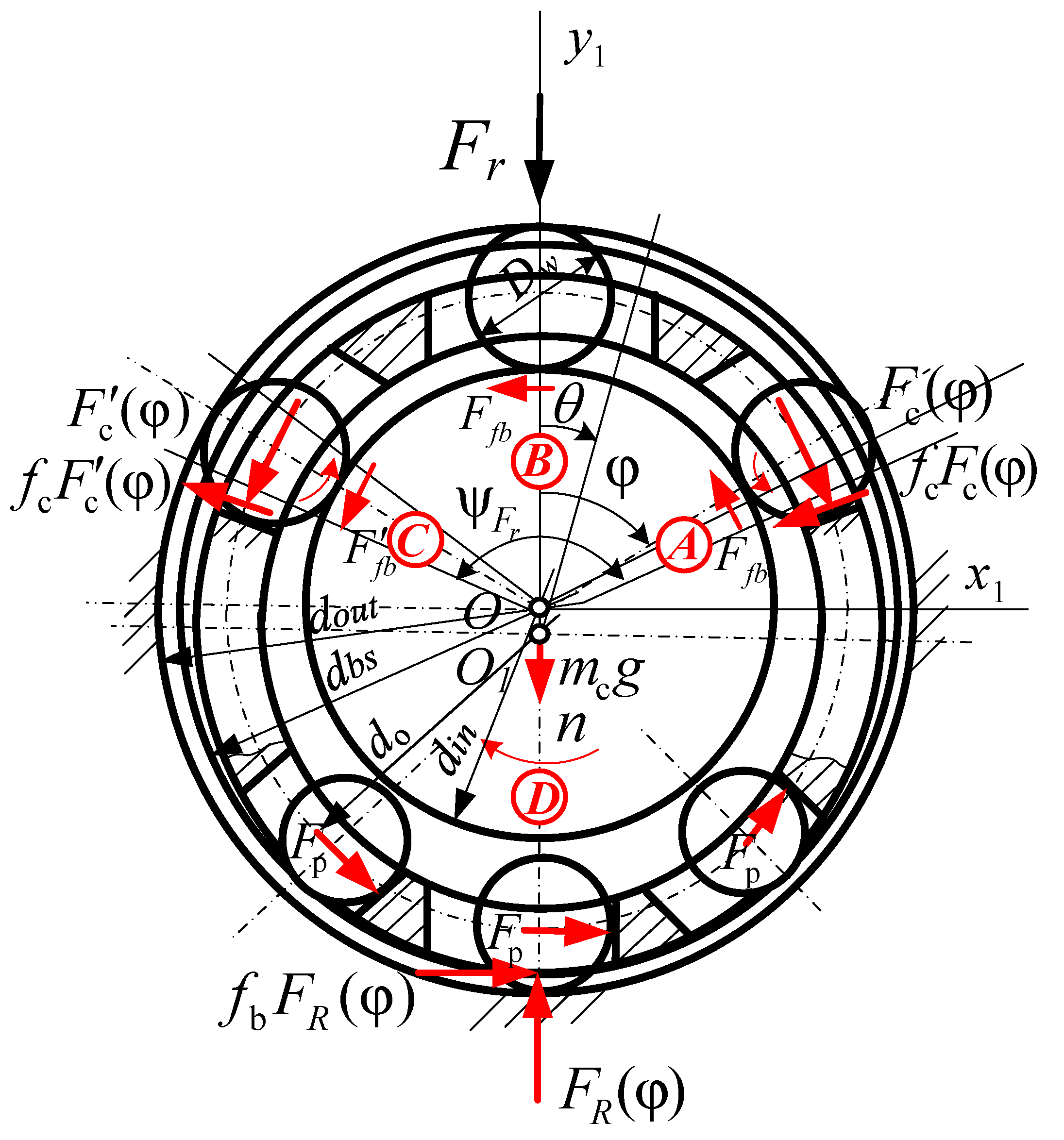
To determine the corresponding pressure forces on the driving and driven rolling elements in the radial load zone, a flat model of the interaction of the rolling elements with the cage is proposed (Figure 1 and Figure 2).
When determining the forces, we relied on the bearing kinematics model developed in [20]. The flat model is built in the zone of the bearing’s radial load, where the transfer of motion from the rolling elements to the cage occurs intermittently because of the gradual reduction of the gaps in the windows of the cage. The transformation of the brake (driven) rolling element, which relies on the movement of the cage, into the driver, which pushes the cage, is carried out in the radial load zone of the bearing. The intermittent nature of the cage’s movement that is caused by the relative difference in the speeds of the cage and the rolling elements leads to shock loading of the cage. This determines the internal dynamics of the rolling bearing.
The force interactions of the cage with the parts of an ideal geometric shape (Figure 1) were considered in the following zones: A—pressing of the driving rolling element on the jumper by force ; B—lack of contact between the rolling elements and the cage; C—pressing the brake (driven) rolling element on the jumper by force ; D—braking of the movement of the cage by rolling elements that are not loaded with radial forces and slide along the raceways under the action of resistance from centrifugal forces .
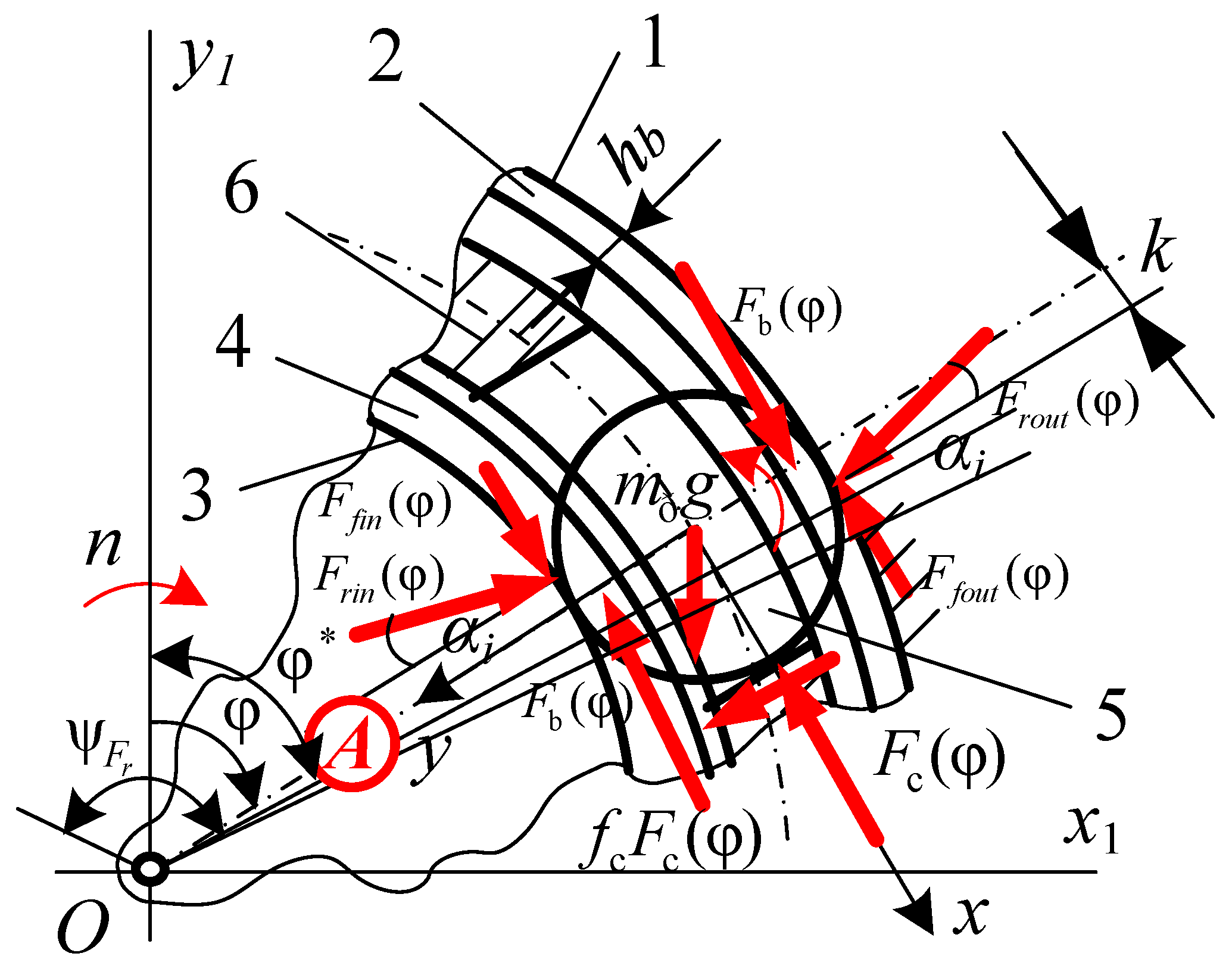
The rolling element of mass , driven by the friction force from the side of the moving inner ring , perceives the resistance of the friction force from the side of the stationary outer ring, the forces of interaction with the cage jumper , and moments from the components of the external load . The system of equations of motion of such an element at the exit from area A of zone (see Figure 2) can be written as follows:
Expressions (6)–(8) are the differential equations of rolling elements motion, expression (9) is the equation of the change in kinetic energy of the rolling element during the movement from the middle of area B to the beginning of area A (see Figure 1), and expression (10) corresponds to the condition of no slippage of the rolling element.
Taking into account that the cage perceives the greatest loads at the beginning of the sliding of the rolling element and having adopted the following designations: —the angle of the beginning of sliding of the rolling element in the zone ; and—the angular positions, —the angular velocities of the rolling element at the beginning and at the end of the movement. By solving the equation of the change in the kinetic energy of the cage during the cycle of its load during the 2S movement, the pressing forces of the driving and driven rolling elements on the jumpers were obtained:
The obtained expressions allow to analytically calculate the energy losses that are due to the design of the cage in the rolling bearing.
2.2. An Energy Efficient Cage Design
With the help of the obtained model, an energy efficiency analysis and modernization of the cage of the cylindrical roller bearing type 2726, installed in the support nodes of the wagons, were carried out. An improved design of the polymer cage was proposed [29]. The cage of a cylindrical roller bearing that contained two rings 1, with cavities 2, and transverse partitions 3, the number of which is equal to the number of pockets 7, partitions 4 with stepped protrusions 5, which is distinguished by the fact that all sides of the seats 7 have a three-wave contour 6, and the convex surfaces of the contours are located in the middle of the cylindrical surfaces and the ends of the rollers, and two or more micro-indentations 8 are made on the friction surface 9 of the rings on the side of each pocket (Figure 3).
When analyzing the energy losses that are due to the design of the cage, temperature gradients for typical and improved cage structures were determined. The calculation of the cooling factor was performed, taking into account the forced external flow of air (blowing) in a single-phase environment with convective heat transfer according to the recommendations [30]. At a given environmental temperature (in summer) , the speed of the train or the rotation frequency of the internal ring , the height of the axle box . Based on the tabular values of the physical properties of dry air: kinematic viscosity ; thermal conductivity ; the number of Prandtl , were received: Reynolds number ; the average Nusselt number the heat transfer coefficient ; the cooling factor . At the speeds of the train, respectively and or the rotation frequency of the internal ring and the cooling factor and and
3. Results and Discussion
The results of calculations of the temperature gradient in the rolling bearings , caused by structural changes in the cage, and corresponding to various operating conditions: ; ; ; (brass on steel); ; (polyamide on steel); are given in Table 1 and in Figure 3.
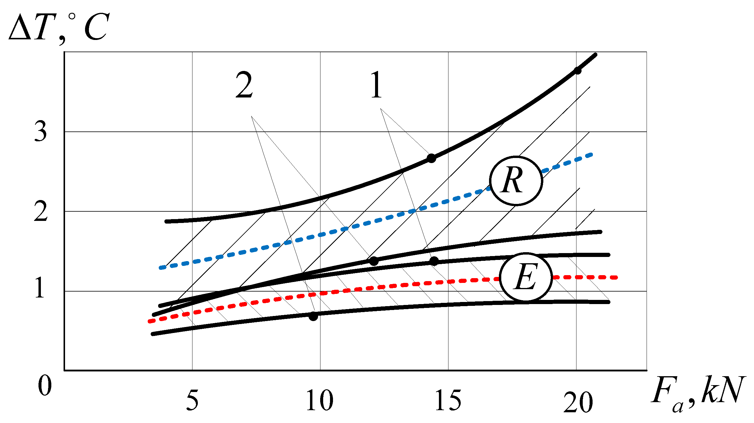
Calculations of the heat generation caused by the separator of typical and modernized bearings for the study range of operation showed both a decrease in both the average level of the temperature gradient and the growth rate of the temperature gradient of the modernized bearings (Figure 4). The temperature gradient of the modernized bearings is 0.4–1.4 °C less than the temperature gradient of typical bearings. Therefore, modernized roller bearings of box cars with an improved cage design maintain a positive tendency to decrease the temperature.
In order to confirm the obtained data, temperature tests were carried out on axle boxes with modernized bearings in one wheel pair of a passenger car attached to the train 59/60 Kharkiv-Odesa (Figure 5). The studies were carried out during a month of train operation along a given route (24 trips).
The proposed heat generation model predicts the value of the temperature gradient in the most loaded part (the upper part of the bearing, in the zone of radial loading). Therefore, during experimental studies, thermocouples were installed in the upper part of the axle box, where the action of the maximum radial loads occurs. Thermocouples (copper/constantan) with a temperature range of have been used. The welded ends of the thermocouples were placed in a grease-lubricated hole in the upper part of the box, as close as possible to the outer ring of the bearings, and a clamping bolt was used to ensure they would not fall out.
Generalized experimental temperature measurements confirmed a 20–60% lower thermal stress compared to the basic analogue. The generalized results of measuring the temperature of the axle box in one of the test trips are shown in Table 2 and in Figure 5.
When comparing the results of the temperature gradient calculations of typical and modernized bearings with the results of their tests in the axle box, one should take into account the many factors that influenced the measurement results. When modeling heat generation in a bearing, the effect of the environment’s static state is taken into account with a constant value of the cooling coefficient (approximately considering the bearing unit) and constant humidity, and the calculated friction forces between the parts have constant values. Under actual operating conditions, the above factors are variable (with unknown laws of change). In the process of testing, new factors of influence on heat generation in the bearing appear, with the most common being: attached masses to the axle box, where there are no longer one, but two bearings; the variable nature of the movement of the car, and hence the cooling of the bearings; different technical condition of the track sections in the forward and reverse directions; variable environmental conditions (temperature, humidity, and pressure). The complexity of considering these many insufficiently studied factors of operational influence does not allow a correlation to be established between the theoretical and experimentally obtained values of heat generation in the bearing. However, the continuing trend of an accelerated increase in the temperature gradient of a typical bearing compared to a modernized one allows us to assert the adequacy of the proposed model for assessing heat generation in a bearing.
At the first stage of the study, a flat model of the bearing was considered. A more accurate calculation is possible if the bearing is imagined as a 3D model. In the 3D model of the bearing, it is possible to take into account the eccentricity of radial and axial loads due to assembly inaccuracies and deformation of parts, to investigate the distortions of not only the rolling elements, but also the design of the cage. These features of load and work will affect the kinematics and dynamics of the bearing. In addition, expressions (11) and (12) are obtained under assumptions about the ideal geometric shape of all parts of the bearing. The results obtained that also use the proposed model require experimental verification. Therefore, special research that considers the above-mentioned factors is required, which may be the subject of the authors’ next publication.
4. Conclusions
The analytical model for evaluating the heat generation of rolling bearings, which is caused by the design of the cage, has been developed. This allows researchers to evaluate the effectiveness of structural improvements and materials, and to establish their effect on the friction forces in the bearing.
With the help of the developed model for assessing heat generation in bearing assemblies, using the example of a cylindrical roller bearing for wheel pairs of passenger cars, a positive trend in reducing the temperature of the axle boxes that is due to the proposed design changes in the bearings is confirmed by increasing the number of rollers, improving the design and replacing the cage material (brass with glass polyamide).
For the studied load range = 30, …, 50 kN, = 5, …, 20 kN) and air blowing speeds = 100, 200, 300 , the temperature gradient of the upgraded bearings 0.4, …, 1.4 °C are less than the temperature gradient of typical bearings.
The experimental results allowed for conclusions about the reliability and validation of the developed model because of the number of experiments that have already been performed.
Author Contributions
Conceptualization, A.G., V.K., and S.D.; methodology, A.G.; software, A.G. and V.K.; validation, Y.B., S.D., D.M. and J.M.; formal analysis, V.K.; investigation, A.G. and V.K.; resources, V.K., Y.B. and A.G.; data curation, J.M.; writing—original draft preparation, A.G. and V.K.; writing—review and editing, Y.B., S.D., D.M. and J.M.; visualization, A.G., V.K., S.D., Y.B. and D.M.; supervision, Y.B. and J.M.; project administration, A.G., V.K. and J.M.; funding acquisition, J.M. All authors have read and agreed to the published version of the manuscript.
Funding
The authors are grateful to FCT—Fundação para a Ciência e Tecnologia (Portugal) who partially financially supported this work through the RD Units Project Scope: UIDP/04077/2020 and UIDB/04077/2020.
Institutional Review Board Statement
Not applicable.
Informed Consent Statement
Not applicable.
Data Availability Statement
Not applicable.
Acknowledgments
The general approach has been partially developed within the research project “Provision of information and consulting services regarding the maintenance, repair and operation of sliding bearings of electric motors of rolling mills Tandem 1680, 1700-1, 1700-2 PJSC ‘Zaporizhstal’ with the development of proposals to increase their reliability” (No. 13994). The experimental research was carried out in cooperation with the Southern Railways Ukraine.
Conflicts of Interest
The authors declare no conflict of interest.
Abbreviations
| Cooling factor | |
| Cage rotation frequency | |
| Cage weight | |
| Cage with the ring friction coefficient | |
| Cage with the rolling element friction coefficient | |
| Rolling element with the ring friction coefficient | |
| Rolling element diameter | |
| Rolling element center diameter | |
| Bearing ring groove radius | |
| Outer ring diameter | |
| Inner ring diameter | |
| Base ring edge diameter | |
| Ring thickness | |
| Rolling friction coefficient | |
| Bearing contact angle | |
| Force of the rolling element with ring interaction | |
| Radial force component from the inner ring | |
| Radial force component from the outer ring | |
| Second moment of inertia | |
| Cage eccentricity |
References
- Klitnoi, V.; Gaydamaka, A. On The Problem of Vibration Protection of Rotor Systems with Elastic Adaptive Elements of Quasi-Zero Stiffness. Diagnostyka 2020, 21, 69–75. [Google Scholar] [CrossRef]
- Gaydamaka, A.; Muzikin, Y.; Klitnoi, V.; Basova, Y.; Dobrotvorskiy, S. Selecting the Method for Pre-tightening Threaded Connections of Heavy Engineering. Int. Conf. Reliab. Syst. Eng. 2021, 305, 69–77. [Google Scholar] [CrossRef]
- Shevchenko, S.; Mukhovaty, A.; Krol, O. Geometric Aspects of Modifications of Tapered Roller Bearings. In Proceedings of the 2nd International Conference on Industrial Engineering, ICIE 2016, Chelyabinsk, Russia, 19–20 May 2016. [Google Scholar] [CrossRef]
- Gaydamaka, A.; Klitnoy, V.; Muzikin, Y.; Tat’kov, V.; Hrechka, I. Construction of a model for the distribution of radial load among the bearing’s rolling bodies. East.-Eur. J. Enterp. Technol. 2018, 6, 39–44. [Google Scholar] [CrossRef] [Green Version]
- Marchenko, A.; Grabovskiy, A.; Tkachuk, M.; Shut, O.; Tkachuk, M. Detuning of a supercharger rotor from critical rotational velocities. In Proceedings of the 4th International Conference on Design, Simulation, Manufacturing: The Innovation Exchange, DSMIE 2021, Lviv, Ukraine, 8–11 June 2021; pp. 137–145. [Google Scholar] [CrossRef]
- Prokopenko, D.; Shatskyi, I.; Vorobiov, M.; Ropyak, L. Cyclic deformation of separating tape in electromagnetic rolling pump. J. Phys. Conf. Ser. 2021, 1741, 012029. [Google Scholar] [CrossRef]
- Jones, A.B. A General Theory for Elastically Constrained Ball and Radial Roller Bearings. Trans. ASME Ser. D J. Basic Eng. 1960, 82, 309–320. [Google Scholar] [CrossRef]
- Yan, K.; Wang, Y.; Zhu, Y.; Hong, J.; Zhai, Q. Investigation on Heat Dissipation Characteristic of Ball Bearing Cage and Inside Cavity at Ultra High Rotation Speed. Tribol. Int. 2016, 93, 470–481. [Google Scholar] [CrossRef]
- Walters, C.T. The Dynamics of Ball Bearings. ASME J. Lubr. Tech. 1971, 93, 1–10. [Google Scholar] [CrossRef]
- Gupta, P.K. Dynamics of Rolling-Element Bearings—Part III: Ball Bearing Analysis. J. Lubr. Technol. 1979, 101, 312–318. [Google Scholar] [CrossRef]
- Gupta, P.K.; Burton, P. Advanced Dynamics of Rolling Elements; Pringer-Verlag Press: New York, NY, USA, 1984. [Google Scholar]
- Kim, S.J. Analytical Consideration of the Radial Clearance to Reduce Cage Slip of the Turbo Engine Roller. Bear. J. Mech. Sci. Technol. 2021, 35, 2827–2839. [Google Scholar] [CrossRef]
- Li, H.; Li, H.; Liu, Y.; Liu, H. Dynamic Characteristics of Ball Bearing with Flexible Cage Lintel and Wear. Eng. Fail. Anal. 2020, 117, 104956. [Google Scholar] [CrossRef]
- Dahiwal, R.; Bernd, S. Investigation of Cage Pocket Wear in Solid-Lubricated Rolling Bearings. Tribol. Online Jpn. Soc. Tribol. 2020, 15, 25–35. [Google Scholar] [CrossRef] [Green Version]
- Bizarre, L.; Nonato, F.; Cavalca, K.L. Formulation of Five Degrees of Freedom Ball Bearing Model Accounting for the Nonlinear Stiffness and Damping of Elastohydrodynamic Point Contacts. Mech. Mach. Theory 2018, 124, 179–196. [Google Scholar] [CrossRef]
- Kwak, W.; Lee, J.; Lee, Y.B. Theoretical and Experimental Approach to Ball Bearing Frictional Characteristics Compared with Cryogenic Friction Model and Dry Friction Model. Mech. Syst. Signal Process. 2019, 124, 424–438. [Google Scholar] [CrossRef]
- Liu, Y.; Wang, W.; Qing, T.; Zhang, Y.; Liang, H.; Zhang, S. The Effect of Lubricant Temperature on Dynamic Behavior in Angular Contact Ball Bearings. Mech. Mach. Theory 2020, 149, 103832. [Google Scholar] [CrossRef]
- Kalinin, Y.; Olexander, S.; Volodymyr, R.; Koliesnik, I.; Kozhushko, A. Determining the Stresses in Beams Due to Short-Term Effect on Their Supports. In Proceedings of the International Conference on Business and Technology, ICBT 2020, Istanbul, Turkey, 14–15 November 2020; pp. 617–628. [Google Scholar] [CrossRef]
- Jiang, S.; Chen, X.; Gu, J.; Shen, X. Friction Moment Analysis of Space Gyroscope Bearing with Ribbon cage Under Ultra-Low Oscillatory Motion. Chin. J. Aeronaut. 2014, 27, 1301–1311. [Google Scholar] [CrossRef] [Green Version]
- Stammler, M.; Schwack, F.; Bader, N.; Reuter, A.; Poll, G. Friction Torque of Wind-Turbine Pitch Bearings–Comparison of Experimental Results with Available Models. Wind. Energy Sci. 2018, 5, 97–105. [Google Scholar] [CrossRef] [Green Version]
- Brecher, C.; Bäumler, S.; Rossaint, J. Calculation of Kinematics and Friction of a Spindle Bearing Using a Local EHL Friction Model. Tribol. Trans. 2013, 56, 245–254. [Google Scholar] [CrossRef]
- Cousseau, T.; Graça, B.; Campos, A.; Seabra, J. Friction Torque in Grease Lubricated Thrust Ball Bearings. Tribol. Int. 2011, 44, 523–531. [Google Scholar] [CrossRef] [Green Version]
- Geonea, I.; Dumitru, N.; Dumitru, I. Experimental and Theoretical Study of Friction Torque From Radial Ball Bearings. IOP Conf. Ser. Mater. Sci. Eng. 2017, 252, 012048. [Google Scholar] [CrossRef] [Green Version]
- Yuwei, L.; Xingyu, F.; Jia, W.; Xiayi, L. An Investigation for the Friction Torque of a Tapered Roller Bearing Considering the Geometric Homogeneity of Rollers. Lubricants 2022, 10, 154. [Google Scholar] [CrossRef]
- Gaydamaka, A. Models of Kinematics and Dynamics of Cylindrical Roller Bearings of Railway Transport. Sci. Transp. Prog. 2014, 3, 100–108. [Google Scholar] [CrossRef] [PubMed] [Green Version]
- Nosov, V.B. Bearing Units of Modern Machines and Devices: Handbook; Mashinostroenie: Moscow, Russia, 1997. [Google Scholar]
- The SKF Model for Calculating the Frictional Moment. 2017. Available online: http://www.skf.com/binary/110299767/The%20SKF%20model%20for%20calculating%20the%20frictional%20moment_tcm_12-299767.pdf (accessed on 6 November 2022).
- Abdan, S.; Stosic, N.; Kovacevic, C.; Smith, I.; Asati, N. Analysis of rolling bearing power loss models for twin screw oil injected compressor. IOP Conf. Ser.: Mater. Sci. Eng. 2019, 604, 012013. [Google Scholar] [CrossRef] [Green Version]
- Gaydamaka, A. Cylindrical Roller Bearing of the Maximum Load within the Specified Dimensions with a Polymer Separator of Onepiece Design. Ukraine Patent Number 91168, 25 June 2014. [Google Scholar]
- Baehr, H.D.; Stephan, K. Heat and Mass Transfer, 2nd ed.; Springer: New York, NY, USA, 2006; 688p. [Google Scholar] [CrossRef]
Figure 1.
The scheme of the interaction of rolling elements with the cage.

Figure 2.
The scheme of force interactions in zone A: 1, 2—outer ring and a rib; 3, 4—inner ring and a rib; 5—rolling body; 6—cage.
Figure 2.
The scheme of force interactions in zone A: 1, 2—outer ring and a rib; 3, 4—inner ring and a rib; 5—rolling body; 6—cage.

Figure 3.
Modernized cage.

Figure 4.
The temperature gradients diagrams for a typical design of a cylindrical roller bearing (region R, z = 14) and a modernized one (region E, z = 16): curve 1—2—.
Figure 4.
The temperature gradients diagrams for a typical design of a cylindrical roller bearing (region R, z = 14) and a modernized one (region E, z = 16): curve 1—2—.

Figure 5.
Graphs of generalized temperature functions T °C depending on the distance L of the passenger car of the Kharkiv-Odesa and Odesa-Kharkiv trains in forward and reverse directions, obtained during a month of research (curve 1—for the typical design of a cylindrical roller bearing; 2—for the modernized design; 3—environment (air); 4—the temperature gradient of the typical design and the environment; 5—the temperature gradient of the modernized design and the environment.


Table 1.
The temperature gradient in the rolling bearings, caused by structural changes in the cage and corresponding to various operating conditions.
Table 1.
The temperature gradient in the rolling bearings, caused by structural changes in the cage and corresponding to various operating conditions.
| 30 | 5 | 110/98 | 99/85 | 578/289 | 0.9/0.5 | 1.1/0.5 | 1.2/0.6 |
| 10 | 147/133 | 139/120 | 791/400 | 1.3/0.6 | 1.5/0.7 | 1.6/0.8 | |
| 15 | 182/167 | 175/156 | 987/510 | 1.6/0.8 | 1.8/0.9 | 1.9/1.0 | |
| 20 | 197/179 | 191/168 | 1073/548 | 1.7/0.9 | 2.0/1.0 | 2.2/1.1 | |
| 40 | 5 | 143/127 | 134/115 | 766/382 | 1.2/0.6 | 1.4/0.7 | 1.5/0.8 |
| 10 | 180/161 | 173/150 | 976/491 | 1.6/0.8 | 1.8/0.9 | 1.9/0.9 | |
| 15 | 215/196 | 210/186 | 1175/604 | 1.9/0.9 | 2.1/1.1 | 2.3/1.2 | |
| 20 | 230/210 | 226/200 | 1261/648 | 2.0/1.0 | 2.3/1.2 | 2.4/1.3 | |
| 50 | 5 | 177/155 | 170/143 | 959/471 | 1.5/0.8 | 1.8/0.9 | 1.9/0.9 |
| 10 | 213/191 | 208/181 | 1164/588 | 1.9/0.9 | 2.1/1.1 | 2.2/1.1 | |
| 15 | 248/224 | 245/214 | 1363/692 | 2.2/1.1 | 2.5/1.3 | 2.6/1.3 | |
| 20 | 263/239 | 261/230 | 1449/741 | 2.3/1.2 | 2.7/1.4 | 2.8/1.4 |
*—in the numerator for a typical bearing with 14 rollers (z = 14), in the denominator for a modernized bearing with 16 rollers (z = 16).
Table 2.
The temperature gradient in the rolling bearings. Generalized experimental results.
| Typical Bearing | Modernized Bearing | ||||
|---|---|---|---|---|---|
| Standard Deviation | Standard Deviation | ||||
| Poltava | 2.96 | 0.43 | 0.92 | 0.12 | 68.9 |
| Kremenchuk | 4.12 | 0.45 | 1.97 | 0.16 | 52.2 |
| Znamyanka | 4.94 | 0.89 | 3.08 | 0.36 | 37.6 |
| Voznesensk | 5.92 | 0.69 | 3.02 | 0.5 | 48.9 |
| Odesa | 4.98 | 0.45 | 1.81 | 0.14 | 63.6 |
| Voznesensk | 2.12 | 0.29 | 0.81 | 0.11 | 61.8 |
| Znamyanka | 3.57 | 0.6 | 2.8 | 0.52 | 21.5 |
| Kremenchuk | 5.07 | 0.93 | 2.78 | 0.4 | 45.1 |
| Poltava | 6.39 | 0.56 | 3.43 | 0.57 | 46.3 |
| Kharkiv | 8.87 | 1.5 | 6.32 | 1.08 | 28.7 |
Disclaimer/Publisher’s Note: The statements, opinions and data contained in all publications are solely those of the individual author(s) and contributor(s) and not of MDPI and/or the editor(s). MDPI and/or the editor(s) disclaim responsibility for any injury to people or property resulting from any ideas, methods, instructions or products referred to in the content. |
© 2023 by the authors. Licensee MDPI, Basel, Switzerland. This article is an open access article distributed under the terms and conditions of the Creative Commons Attribution (CC BY) license (https://creativecommons.org/licenses/by/4.0/).
Share and Cite
MDPI and ACS Style
Gaydamaka, A.; Klitnoi, V.; Dobrotvorskiy, S.; Basova, Y.; Matos, D.; Machado, J. A Systematic Approach for Energy-Efficient Design of Rolling Bearing Cages. Appl. Sci. 2023, 13, 1144. https://doi.org/10.3390/app13021144
AMA Style
Gaydamaka A, Klitnoi V, Dobrotvorskiy S, Basova Y, Matos D, Machado J. A Systematic Approach for Energy-Efficient Design of Rolling Bearing Cages. Applied Sciences. 2023; 13(2):1144. https://doi.org/10.3390/app13021144
Chicago/Turabian StyleGaydamaka, Anatoliy, Volodymyr Klitnoi, Sergey Dobrotvorskiy, Yevheniia Basova, Demétrio Matos, and José Machado. 2023. "A Systematic Approach for Energy-Efficient Design of Rolling Bearing Cages" Applied Sciences 13, no. 2: 1144. https://doi.org/10.3390/app13021144
Note that from the first issue of 2016, this journal uses article numbers instead of page numbers. See further details here.