


Finite Element Simulation of a Multistage Square Cup Drawing Process for Relatively Thin Sheet Metal through a Conical Die
1
Department of Industrial Engineering, Faculty of Engineering, Jazan University, Jazan 82817, Saudi Arabia
2
Mechanical Production Department, Faculty of Technology and Education, Beni-Suef University, P.O. Box 62521, Beni-Suef 62511, Egypt
3
Mechanical Design and Production Engineering Department, Faculty of Engineering, Assiut University, Assiut 71516, Egypt
*
Author to whom correspondence should be addressed.
Processes 2024, 12(3), 525; https://doi.org/10.3390/pr12030525
Submission received: 6 February 2024
/
Revised: 28 February 2024
/
Accepted: 3 March 2024
/
Published: 6 March 2024
(This article belongs to the Special Issue Simulation, Modeling, and Decision-Making Processes in Manufacturing Systems and Industrial Engineering)
Abstract
:A new manufacturing process has been developed that involves drawing circular sheets of thin metal through a conical die to create square cups. This technique produces deep square cups with a height-to-punch-side length ratio of approximately 2, as well as high dimensional accuracy and a nearly uniform height. The study investigated how various factors, including the sheet material properties and process geometric parameters, affect the limiting drawing ratio (LDR). The researchers used finite element analysis to determine the optimal die design for achieving a high LDR and found that the proposed technique is advantageous for producing long square cups with high dimensional accuracy.
1. Introduction
Square cups made of thin sheet metal are widespread across various industrial fields. They are utilised in automotive engineering, production lines, container construction, building construction, household appliances, and packaging industries. This process offers numerous benefits, including high productivity and the ability to create complex shapes. However, the process involves a complicated deformation mechanism, and the quality of the deformed cups and process efficiency depends on various parameters, such as punch shape factors, die geometry, blank shapes, sheet thickness, blank holding force, blank materials, friction, and lubrication. Hence, identifying the impacts of these parameters on the square cup deep drawing process can help develop better control strategies for optimising the process.
During the square cup deep drawing process, blanks are typically held against the die’s face using a rigid blank holder plate to prevent wrinkles in the flange. However, this approach can lead to non-axisymmetric metal flow rates along the straight walls and around the corners, resulting in uneven material distribution around the cup walls. This flow non-uniformity can create local contact zones with an increased surface pressure due to the increased sheet thickness in the corner zones, leading to deformation concentration in the cup corners and cup fracture [1,2,3,4]. Controlling the material flow rate into the die cavity is crucial to prevent these issues; this can be achieved by optimising the blank holder force, which can help regulate the metal flow and improve the quality of the square cup drawing process.
Various solutions have been proposed to address the non-uniformity of the metal flow into the die cavity, including changing the material properties of the sheet metal, altering the frictional state, optimising the blank shape, and designing flexible blank holding systems. Many innovative blank-holding systems have recently been proposed to improve performance and deep drawability.
There are three distinct approaches to enhancing the drawability of square cups. The first involves enhancing the material properties of the sheet metal used in the forming process. The second approach improves process parameters, including the friction and lubrication conditions, tool geometries, optimum blank shape, material properties, and form temperature. Finally, the third category centres on altering the deformation zone’s stress state and instability condition. This third approach is recommended for increasing the limiting drawing ratio of square cups.
Pliable blank holder systems, introduced by Doege et al. [5,6], are designed with elastically deformable thin steel plates to allow for deflection. This innovative design ensures that pressure is evenly distributed across the blank regardless of changes in thickness. Yagami et al. [7] utilised separate segmented binders, each operated using a hydraulic cylinder with a unique binder force profile. Meanwhile, Hassan et al. [8] proposed a method for deep drawing with friction aided by a segmented blank holder. This holder is constructed with stiff segments connected by elastic joints. Lastly, Gavas et al. [9] suggested a blank holder system equipped with a spiral spring at the side in contact with the blank to be drawn. These techniques have been found to improve the material flow and formability.
In their paper, Venkatesh and Goh (1998) [10] explored the Guerin and Marform processes, which utilise rubber pads as pressure media and emphasise the innovation and development of new techniques. While these techniques can yield a superior surface finish and are versatile enough to accommodate a range of component materials, their cost-effectiveness is limited to short production runs and not well suited to mass production. It should be noted that the LDR achieved using these methods is larger than what is commonly achieved through conventional means, and they require a greater forming force to achieve successful deep drawing. In 1995, Sato et al. [11] proposed a multi-axial loading technique utilising a punch and four side tools for drawing thick deep square cups. This method leads to an increased LDR compared to the conventional method when working with thick sheets, as the thinning of the drawn cups at the punch profile radius is reduced. However, the maximum load required is still higher than the conventional methods, and the process is more complex. Lang et al. (2004) [12] conducted a study and found that hydromechanical deep drawing with hydraulic counter pressure offers several advantages compared to conventional square cup forming methods. This process creates high drawing ratio parts (3.44) with an impeccable surface quality and precise dimensions, even for intricate shapes. However, it requires significant forming forces and specialised equipment and only works with thin sheet materials. Explosive forming is a technique commonly used for shaping large, complex forms and has been utilized to create square cups. Wijayathunga and Webb (2006) [13] found that the process is complicated, and the drawing ratio is limited, which requires extensive experimentation and FE simulation to achieve uniform square cups with a considerable drawing ratio. Mustafa et al. (2007) [14] developed a test set to assess the drawability limits of gradually rectangular-shaped containers in a multi-point deep drawing process for 3D sheet metal parts. They used a multi-point forming technology with a given tool geometry and drawing velocity. The authors discovered that this technique reduces the die production costs, offers flexible usage, and achieves even deformation distribution. However, the setup process is complicated, and pitting defects may occur due to the concentrated load at individual punches during forming, leading to localised deformation and limiting the drawability of the sheet metal. In 2015, Walid et al. [15] introduced a modern method of producing a square shape by changing the geometric shape of the die, using a conical die with a square aperture and square punch. This method aims to obtain a product with the highest drawing ratio limit compared to the traditional method of using a square die and punch to produce a square shape. Furthermore, this method eliminates the defects associated with the traditional method.
Hassan et al. (2012) [16] introduced a divided blank holder featuring a tapered base and eight tapered segments, aiming to enhance the deep drawability of square cups. Their study showed the superiority of deep drawing compared to the traditional methods when working with thin sheets and foils. However, they found that the deep drawability significantly decreased when working with thicker sheets. Hezam et al. (2009) [17] developed an innovative method to enhance the deep drawability of square cups, utilising a conical die equipped with a square aperture at its end, allowing for the seamless flow of the metal from the circular sections to the square aperture and throat of the die. The technique has shown promising results in increasing the drawing ratio, particularly for thicker sheets. However, further research is needed to optimise the setup dimensions and operating conditions to achieve the highest possible LDR. Additionally, gaining a better understanding of the process and its deformation characteristics is crucial, as the quality of the deformed cups and the efficiency of the process depend on optimal selection of the forming parameters. Adnan (2022) [18] compared two methods for producing complex shapes: direct and indirect. They found that the indirect method outperformed the direct method in terms of a lower drawing force, better thickness distribution, and more favourable stress and strain distribution. However, the direct method may not be suitable for complex shapes requiring multiple drawing stages, as it can be challenging to ensure proper centering between the die and the product.
Despite advancements in deep drawing techniques, they still have limitations compared to the traditional methods. Most techniques yield limiting drawing ratios of around 2, which only allows for a cup height-to-diameter ratio of approximately 1. Maximising the deep drawability in square cup drawing processes is critical to reducing manufacturing costs and time. The sheet metal’s drawability depends on its ability to flow effortlessly in the plane of the sheet’s flange region and resist deformation in the thickness direction. Given the limitations mentioned earlier, there is still a need to overcome them, improve the material flow, and increase the deep drawability. This study aims to design a new technique for creating a square cup by drawing a circular blank of relatively thin sheet metal (0.75 to 1.5 mm) through a conical die. The technique offers several advantages, including a simple deformation mechanism, simplified drawing tools, and reduced power requirements for forming. Since single-action presses can be used to perform the process, drawing beads or blank holder forces are unnecessary. The study used finite element analysis to investigate the sheet metal’s deformation behaviour during the drawing process.
2. The Proposed Method for Square Cup Drawing of a Thin Sheet
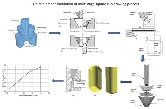
Deep drawing of square cups without a blank holder is possible using the proper die geometry, such as a conical die and a suitable punch with a suitable side length/sheet thickness ratio (Lp/to). Hassab-Allah et al. [19] designed a new technique for square cup drawing of relatively thick sheets (Lp/to < 30). In the study in [20], some restrictions and optimum circumstances have been reported for deep drawing using a conical die. It was shown that fewer drawing stages and simple die sets needed for producing long square cups can be obtained with very high drawing ratios. Furthermore, deep drawing can be carried out in single-action presses. Unfortunately, when using the same technique described in [21] for drawing a square cup of a relatively thin sheet, i.e., drawing with high values of Lp/to (Lp/to > 30), wrinkling commonly occurred at the early stage of drawing due to the compressive hoop stresses induced in the flange of the cup. This is because the strength of a relatively thin sheet blank is insufficient to restrict buckling due to its buckling stiffness. The maximum drawing ratio in the deep drawing of square cups, without a blank holder, is restricted for thin sheets by the wrinkling or buckling of the flange or the cup walls. If wrinkles are avoided at the beginning of the deep drawing process, relatively high deep drawing ratios can be obtained. As a result of the wrinkling tendency, the flange’s inherent stiffness at the beginning of the drawing stage can be enhanced by using an auxiliary drawing tool. In the proposed method, the forming of wrinkles at the early stage of drawing and during the drawing process can be avoided by using a tapered punch, as shown in Figure 1. The proposed technique is based on the same idea of deep drawing without a blank holder through a conical die except using an extra drawing tapered punch. The square cup can be drawn by pushing the circular blank without a blank holder through a conical die. The conical die used in the proposed method contains a square aperture at the die exit; see Figure 1. The advantage of using a conical die is a decrease in the frictional force compared with that in the conventional deep drawing process since the sheet is in contact with the tool on one side only. Furthermore, the load resulting from bending and unbending is reduced owing to the more favourable shape of the die. However, in the conventional square cup deep drawing process, the blank is bent through a right angle as it passes over the die entry radius and then has to be unbent as it is straightened. Therefore, in the drawing through a conical die, the force available for plastic deformation is greater, and the maximum blank size is increased. Figure 2 shows the forming sequences during the square cup drawing through a conical die. During the cupping stage, in Figure 2a, the outer perimeter of the circular blank is forced into compression by the cupping action. The conical surface of the die cavity supports the outer edge of the blank during cupping, thus frequently preventing wrinkling. In the cupping stage, the blank is bent simply around the corners of the tapered punch, and the blank flange comes into contact with the die wall and conforms to its profile. Unlike the conventional deep drawing process, no unbending action is taken, producing a less work-hardened partially drawn frustum conical cup; see Figure 2a. The remaining ductility in the partially drawn frustum cup walls leads to considerable forming that can be achieved after the cupping stage without inter-stage annealing. The motion of the square and tapered punches are coupled during the cupping stage. At the end of the cupping stage, the circular blank was deformed into a frustum conical cup; see Figure 2a. The tapered punch acts as the blank holder with constant gap clearance during the square cup drawing stage. However, there is no need to apply force or pressure over the tapered punch; the tapered punch must be fixed at its end position. The flat-headed square punch pushes the bottom of the partially drawn frustum conical cup into the square aperture at the die exit, drawing it into a square cup; see Figure 2b. The plastic instability caused by compressive hoop stresses may also occur in the unsupported cup wall area between the tapered punch and die during the cupping stage. This plastic instability can be enhanced using a suitable end diameter for the tapered punch. The half cone angle of both the die and the tapered punch is also important in controlling the wrinkling in the unsupported cup wall area during the cupping stage, especially in the case of a relatively thin sheet. The best selection of half cone angle can enhance the buckling stiffness and increase the limiting drawing ratio.
3. FEM Simulation of the Proposed Process
The geometrical parameters of the drawing die set are shown in Figure 3. Because many process parameters can influence the square cup’s deep drawing, it is difficult to find the optimal process parameters and manufacture the drawing tools. Therefore, FE simulation was adopted to investigate the influences of those parameters. In the present work, the FE simulations have been carried out with the explicit elastic–plastic FE code DYNAFORM-PC. Figure 4 shows the mesh system for the complete tooling and sheet blank set used in the square cup’s deep drawing. Owing to the geometric symmetry conditions, only a quarter model of the square cup was analysed. A quarter of the circular blank was initially meshed with 541 nodes and 500 elements, as shown in Figure 5. The remeshing generation module was adopted to completely describe the deformed blank’s contour during the drawing process. For the FE simulation, the drawing tools are considered rigid, and the corresponding meshes used to define the tooling geometry are not for stress analysis. Due to the high elastic modulus of the drawing tools, a perfectly rigid surface is assumed, which is an acceptable approximation since the elastic deflection of the drawing tools is relatively negligible compared with the excessive plastic deformation of the blank. Rigid shell elements have been used to simulate the drawing tool surfaces to decrease the computing times. The drawing tools, tapered punch, square punch, and die were modelled using rigid 4-node shell elements with surface-to-surface contact for the interface between the circular blank and the drawing tools, while the circular blank was modelled using 4-node deformable shell elements.
The deep drawing process is simulated by moving the tapered and square punches down to push the circular blank into the die cavity. The speed of both punches is set to be 5 m/s, while the conical die is completely fixed. The tapered and square punches are moved together at the beginning of the drawing process until the frustum conical cup is drawn, as shown in Figure 2a. After that, only the square punch is further moved down to complete the drawing of the square cup, as shown in Figure 2b. The strain-hardening behaviour of the blank material is described in the FE simulations according to the power law (Hollomon’s law): σ = 500 εn with different values for the strain-hardening exponent n of 0.1, 0.2, 0.25, 0.3, 0.4, and 0.5. The anisotropic behaviour of sheet metal has been represented using the average normal anisotropy (Lankford value R) with different values, 1.25, 1.5, 1.75, 2, and 2.25, to study the benefit of its values in the drawing of square cups.
The elastic properties of the blank material are Young’s modulus E = 210 GPa and Poisson’s ratio ν = 0.3. To study the effect of the initial sheet thickness and the drawing set geometric parameters on the limiting drawing ratios, different values of initial sheet thicknesses (to = 0.75, 1, 1.25, and 1.5 mm) and die half cone angles (α = 20, 25, 30, 35, and 40°) were used in the FE simulation models. Square flat-headed punches with a side length Lp of 45 mm; punch nose radius rp of 5 mm; and different values of corner radii rpc = 4.5, 9, 13.5, 18 and 22.5 mm, which are equivalent to square punch shape factors rpc/Lp = 0.1, 0.2, 0.3, 0.4, and 0.5, were used. The gap clearance (c) between the square punch and conical die aperture was kept constant, equal to 1.25. The same clearance value was used for the gap between the tapered punch and conical die. The square die aperture has a corner radius rdc = rpc + c. The used geometrical parameters of the tapered punch are a nose radius of 10 mm and different values of end diameter dtp = 63, 67.5, 72, and 76.5 mm (which give tapered punch diameter ratios dtp/Lp = 1.4, 1.5, 1.6, and 1.7, respectively). The drawing ratio (DR) is defined as the ratio of the initial diameter of a circular blank (Do) to the square punch side length (Lp). The limiting drawing ratio (LDR) is the maximum drawing ratio of the blanks that can be drawn without failure. Constraints on the thickness variation must be applied to obtain a drawn cup without defects such as ruptures or wrinkles. Obtaining a square cup without defects requires some restrictions on the cup wall thickness strain to avoid plastic instability. The limitation constraints on the sheet thickness variation can be expressed using the following criteria [20,21]:
where to and t are the initial and current sheet thicknesses. The law of constant friction is assumed at the drawing tools–workpiece interface, and the coefficient of friction remains constant during the process. Contact with Coulomb friction law is used, in which the average friction coefficients between the contacting surfaces of the blank and the square punch, tapered punch, and die are taken to be 0.25, 0.05, and 0.05, respectively.
4. Results and Discussion
4.1. Effect of Sheet and Geometric Parameters of the Drawing Sets on the LDR
In this part of the FE simulation results, the effect of the process geometric parameters, sheet thickness, half cone angle, tapered punch diameter ratio (dtp/Lp), and square punch shape factor (rpc/Lp) on both the deformation characteristic and deep drawability of sheet metal are investigated. In order to examine the effect of these geometric parameters on the limiting deep drawing ratios, blanks of different sheet thicknesses and different outer diameters were drawn through deep drawing tool sets of different geometric parameter values. The drawing continued with an increasing blank outer diameter until defects such as ruptures or wrinkles occurred. The values of the blank outer diameter increased until either one of the two modes of failures occurred, i.e., the sheet thickness at the punch corner reached a predetermined critical value (75% of its initial value) or thickening at the blank outer circumferential reached a predetermined critical value (115% of its initial value). The maximum value of the blank outer diameter drawn into a square cup without failure was used as the formability index, and the limiting drawing ratio (LDR) was calculated based on its value. Figure 6 shows the predicted limiting deep drawing ratio variation with the initial sheet thickness. It can be noted that the LDR increases with an increase in the initial sheet thickness due to the increase in buckling stiffness with the increase in blank thickness, which suppresses the occurrence of wall wrinkling. In this proposed technique, only the blank buckling stiffness suppresses the wrinkling because there is no blank holder.
The half cone angle α significantly impacts the limiting drawing ratio, as demonstrated in Figure 7. Increasing the half cone angle leads to a drastic increase in the limiting drawing ratio. However, for die half cone angles greater than 35°, the limiting deep drawing ratio decreases with an increasing α due to premature and severe wrinkling. It is worth noting that an optimal half cone angle exists for drawing square cups, falling within the range of 30° to 35°. This type of premature and severe wrinkling occurs at the unsupported region and cannot be suppressed since the blank is not in place. This initial wall wrinkling typically starts at the blank circumferential, see Figure 8. Figure 9 illustrates how LDR’s predicted limiting drawing ratio varies with the tapered punch diameter ratio dtp/Lp. The LDR increases as dtp/Lp increases until it reaches 1.6 and then decreases with further increases in dtp/Lp. The decreasing limiting deep drawing ratio for high values of dtp/Lp > 1.6 is due to the cup wall wrinkling formed at the edge of the cup wall near the end of the drawing stage, as shown in Figure 10.
In the cases of deep drawing with high values of dtp/Lp, i.e., large tapered punch end diameter dtp values, the distance between the tapered punch head (at their end stroke) and the square die aperture is insufficient. So, the wall of a partially drawn cup in the unsupported free zone, in Figure 10a, becomes unstable due to circumferential compressive stresses. Therefore, the partially drawn cup becomes free to wrinkle if the circumferential compressive stress developed in the cup wall exceeds the buckling stress limit for the material to be drawn. The simulation results show that wrinkling occurred at the top of the cup wall, and the simulated shape of the wrinkled drawn cup is shown in Figure 10b. It can be seen that the wrinkles are located along the side walls of the cup. Consequently, increasing the end diameter of the tapered punch will cause more severe wrinkling. A common characteristic of these two types of wall wrinkling shown in Figure 8 and Figure 10a is that wrinkles are found at the draw wall, occurring in the unsupported free zones. The successfully simulated drawn cup is shown in Figure 10c. It is worth noting that the successfully obtained cup has a nearly uniform cup height all around the cup cross-section. The limiting drawing ratio is greatly affected by the punch shape factor, rpc/Lp [4]. Figure 11 shows the predicted limiting drawing ratio (LDR) variation with the punch shape factor. It is clear that the limiting drawing ratio (LDR)increased drastically with the increasing punch shape factor; similar results are reported in [4]. The decreasing limiting drawing ratio for small punch corner radius values (i.e., small punch shape factor values) can be attributed to the severe wrinkles formed at the die corner due to the excessive metal flow in small corner regions, and the corner zone cannot absorb all the excessive material that will pass through it. The limiting drawing ratio increased with an increasing punch shape factor until rpc/Lp = 0.2, and a further increase in rpc/Lp leads to a decrease in the limiting drawing ratio. The decreasing limiting drawing ratio for larger values of rpc/Lp ≥ 0.2 is attributed to the increased deformation concentration at the punch corners. This leads to severe thinning at the punch corners, and the cup wall becomes insufficient to sustain the drawing loads. Wrapping the sheet metal to be drawn over the rounded corner square head reduces the deformation concentration at the punch nose. The increase in the corner radius leads to an increase in the deformation concentration. In contrast, the extra decrease in the corner radius causes the flow of the sheet metal and wrinkling at the die corner. Therefore, an optimum punch corner radius value prevents both walls from wrinkling at the die corner and the deformation concentration over the punch nose. For the process parameters in Figure 11, the optimum punch shape factor equals 0.2, i.e., the optimum punch corner radius is 9 mm. Deep drawing with a shape factor rpc/Lp = 0.5 represents the conventional deep drawing for a circular cup. From Figure 11, it is worth noting that the drawing with a 0.2 punch shape factor increased the LDR by about 6% compared to the LDR obtained using conventional circular cup deep drawing.
4.2. Effect of Sheet Material Properties on the LDR
The results displayed in Figure 12 exhibit the relationship between the predicted limiting drawing ratio (LDR) and the average standard anisotropy R-value. The LDR increased as the average R-value increased, indicating that high R-values can effectively minimise the thinning at the corner wall regions of the punch profile edge and the thickening at the cup wall. These findings demonstrate the benefits of utilising high R-values in drawing square cups.
Additionally, Figure 13 highlights the predicted LDR variation with the strain-hardening exponent n. It is worth noting that the LDR increased as n increased until n = 0.25. Increasing the strain-hardening exponent within the first zone of the curve (0.1 < n < 0.25) can prevent the instability caused by wrinkling at the beginning of the drawing operation. However, increasing the strain-hardening value (n > 0.25) decreased the LDR due to an increase in the thinning over the punch head corner. Based on the process parameters illustrated in Figure 13, an optimum strain-hardening exponent of n = 0.25 exists for drawing square cups.
5. Conclusions
A novel technique using metal was proposed for drawing relatively thin sheets into square cups through conical dies. The DYNAFORM-PC finite element code was utilised to perform the simulation. The package used to simulate sheet metal forming was based on LS-DYNA. The analysis aimed to investigate the deformation behaviour and defect prediction during the process. The results of this investigation revealed the following:
- The proposed technique significantly increases the limit drawing ratio (LDR) and improves the flow of blank material within the die throat.
- The proposed technique can significantly reduce the loads required for drawing instead of conventional deep drawing.
- For anisotropic sheet metal, orienting the circular blank to be drawn where the cup diagonal corresponds to the direction of the greatest R-value and greatest yield stress can further improve the LDR.
- An optimum die design to obtain a high limiting drawing ratio was determined using the FE analysis.
- There is no need for draw beads, a blank holding force, or blank design optimization.
Author Contributions
Conceptualization, I.M.H.-A.; Software, I.M.H.-A.; Validation, W.M.S.; Formal analysis, W.M.S. All authors have read and agreed to the published version of the manuscript.
Funding
This research was funded by the Deputyship for Research and Innovation, the Ministry of Education in Saudi Arabia, project number ISP-2024.
Data Availability Statement
The data presented in this study are available on request from the corresponding author.
Conflicts of Interest
The authors declare that they have no known competing financial interests or personal relationships that could have appeared to influence the work reported in this paper.
References
- Marumo, Y.; Saiki, H.; Mori, T. Combined effects of strain hardening characteristics and the geometry on the deep-drawability of square aluminum cup. J. Mater. Process. Technol. 1999, 89–90, 30–36. [Google Scholar] [CrossRef]
- Marumo, Y.; Saiki, H. Evaluation of the forming limit of aluminum square cups. J. Mater. Process. Technol. 1998, 80–81, 427–432. [Google Scholar] [CrossRef]
- Kuwabara, T.; Akiyama, K.; Nakayama, Y. Square shell drawing characteristics of aluminum alloy sheet A5182-O. J. Mater. Process. Technol. 1993, 38, 737–749. [Google Scholar] [CrossRef]
- Kawai, N.; Mori, T.; Hayashi, H.; Kondoh, F. Effects of punch cross-section on deep drawability of square shell of square shell of aluminum sheet. J. Eng. Indus. 1987, 109, 355–361. [Google Scholar] [CrossRef]
- Doege, E.; Eland, L.E.; Ropers, C. Pliable blank holder systems for the optimization of process conditions in deep drawing. In Advanced Technology of Plasticity 99, Proceedings of the 6th International Conference on Technology of Plasticity Nuremberg, 19–24 September 1999; Springer: Berlin/Heidelberg, Germany, 1999; pp. 177–182. [Google Scholar]
- Doege, E.; El, L.E. Design and application of pliable blank holder systems for the optimization of process conditions in sheet metal forming. J. Mater. Process. Technol. 2001, 111, 182–187. [Google Scholar] [CrossRef]
- Yagami, T.; Manabe, K.; Yang, M.; Koyama, H. Intelligent sheet stamping process using segment blank holder modules. J. Mater. Process. Technol. 2004, 155–156, 2099–2105. [Google Scholar] [CrossRef]
- Hassan, M.A.; Abouel-Kasem, A. A novel friction aided deep drawing process for producing deep square cups. In Proceedings of the Eight Cairo University Conference MDP-8 on Mechanical Design and Production, Cairo, Egypt, 4–6 January 2004; pp. 961–968. [Google Scholar]
- Gavas, M.; Izciler, M. Design and application of blank holder system with spiral spring in deep drawing of square cups. J. Mater. Process. Technol. 2006, 171, 274–282. [Google Scholar] [CrossRef]
- Venkatesh, V.; Goh, T. A note on mathematical models of cup drawing by the Guerin and Marform processes. J. Mech. Work. Technol. 1998, 13, 273–278. [Google Scholar] [CrossRef]
- Sato, E.; Shimizu, T.; Sano, T.; Fuchizawa, S. Effect of multi-axial loading path on limiting drawing ratio. J. Mater. Process. Technol. 1995, 63, 60–65. [Google Scholar] [CrossRef]
- Lang, L.; Danckert, K.; Nielsen, B.; Zhou, X. Investigation into the forming of a complex cup locally constrained by around die based on an innovative hydromechanical deep drawing method. J. Mater. Process. Technol. 2004, 167, 191–200. [Google Scholar] [CrossRef]
- Wijayathunga, V.; Webb, D. Experimental evaluation and finite element simulation of explosive forming of a square cup from a brass plate assisted by a lead plug. J. Mater. Process. Technol. 2006, 172, 139–145. [Google Scholar] [CrossRef]
- Yaşar, M.; Korkmaz, Z.; Gavas, M. Forming sheet metals by means of multi-point deep drawing method. Mater. Des. 2007, 28, 2647–2653. [Google Scholar] [CrossRef]
- Shewakh, W.M.; Hassan, M.A.; Hassab-Allah, I. Square-Cup Deep Drawing of Relatively Thick Sheet Metals Through a Conical Die without Blank Holder. Int. J. Mater. Form. Mach. Process. 2015, 2, 31–46. [Google Scholar]
- Hassan, M.; Ahmed, K.; Takakura, N. A developed process for deep drawing of metal foil square cups. J. Mater. Process. Technol. 2012, 212, 295–307. [Google Scholar] [CrossRef]
- Hezam, L.; Hassan, M.; Hassab-Allah, I.; El-Sebaie, M. Development of a new process for producing deep square cups through conical dies. Int. J. Mach. Tools Manuf. 2009, 49, 773–780. [Google Scholar] [CrossRef]
- Mohammed, A.I. Effect of Forming Method on the Behavior of the Drawing Process of a Complex Shape. Iraqi J. Ind. Res. 2022, 9, 1–11. [Google Scholar] [CrossRef]
- Hassab-Allah, I.M.; Hezam, L.M.A.; El-Sebaie, M.G. A novel forming technology for drawing square cups. In Proceedings of the Production Engineering & Design for Development, PEDD7, Cairo, Egypt, 7–9 February 2006; pp. 948–960. [Google Scholar]
- Naceur, H.; Guo, Y.; Batoz, J. Blank optimization in sheet metal forming using an evolutionary algorithm. J. Mater. Process. Technol. 2004, 151, 183–191. [Google Scholar] [CrossRef]
- Sheng, Z.; Jirathearanat, S.; Altan, T. Adaptive FEM simulation for prediction of variable blank holder force in conical cup drawing. Int. J. Mach. Tools Manuf. 2004, 44, 487–494. [Google Scholar] [CrossRef]
Figure 1.
Pictorial representation of the drawing set and circular blank used for the square cup drawing process.
Figure 1.
Pictorial representation of the drawing set and circular blank used for the square cup drawing process.

Figure 2.
Sequences of square cup drawing through a conical die. (a) frustum conical cup drawing; (b) square cup drawing.
Figure 2.
Sequences of square cup drawing through a conical die. (a) frustum conical cup drawing; (b) square cup drawing.

Figure 3.
Geometrical description of the tooling for the deep drawing of square cup.

Figure 4.
Quarter FE meshes for the blank and drawing tools.

Figure 5.
Initial FE mesh system for the quarter blank.

Figure 6.
Variation in predicted LDR with the initial sheet thickness to (dtp/Lp = 1.6, α = 30°, n = 0.25, R = 2, K = 500 MPa, rpc/Lp = 0.2, µd = µtp = 0.05, and µp = 0.25).
Figure 6.
Variation in predicted LDR with the initial sheet thickness to (dtp/Lp = 1.6, α = 30°, n = 0.25, R = 2, K = 500 MPa, rpc/Lp = 0.2, µd = µtp = 0.05, and µp = 0.25).

Figure 7.
Variation in predicted LDR with the half cone angle α (dtp/Lp = 1.6, to = 1 mm, n = 0.25, R = 2, K = 500 MPa, rpc/Lp = 0.2, µd = µtp = 0.05, and µp = 0.25).
Figure 7.
Variation in predicted LDR with the half cone angle α (dtp/Lp = 1.6, to = 1 mm, n = 0.25, R = 2, K = 500 MPa, rpc/Lp = 0.2, µd = µtp = 0.05, and µp = 0.25).

Figure 8.
Premature wrinkling of the blank to be drawn over the die surfaces with large half-cone angle.
Figure 8.
Premature wrinkling of the blank to be drawn over the die surfaces with large half-cone angle.

Figure 9.
Variation in predicted LDR with the punch diameter ratio dtp/Lp (α = 30°, R = 2,. n = 0.25, K = 500 MPa, rpc/Lp = 0.2, µd = µb = 0.05, t = 1 mm, and µp = 0.25).
Figure 9.
Variation in predicted LDR with the punch diameter ratio dtp/Lp (α = 30°, R = 2,. n = 0.25, K = 500 MPa, rpc/Lp = 0.2, µd = µb = 0.05, t = 1 mm, and µp = 0.25).

Figure 10.
Cup wall wrinkling at the end of deep drawing process; (a) drawing tool set with high dtp/Lp shows cup wall wrinkling in the unsupported free zone, (b) simulated drawn cup with wrinkles at the edge of cup wall, and (c) simulated successfully drawn cup, free from wrinkles.
Figure 10.
Cup wall wrinkling at the end of deep drawing process; (a) drawing tool set with high dtp/Lp shows cup wall wrinkling in the unsupported free zone, (b) simulated drawn cup with wrinkles at the edge of cup wall, and (c) simulated successfully drawn cup, free from wrinkles.

Figure 11.
Variation in predicted LDR with the punch shape factor rpc/Lp (dtp/Lp = 1.6, α = 30°, t = 1 mm, R = 2, n = 0.25, K = 500 MPa, µd = µtp = 0.05, and µp = 0.25).
Figure 11.
Variation in predicted LDR with the punch shape factor rpc/Lp (dtp/Lp = 1.6, α = 30°, t = 1 mm, R = 2, n = 0.25, K = 500 MPa, µd = µtp = 0.05, and µp = 0.25).

Figure 12.
Variation in predicted LDR with the average normal anisotropy R-value (dtp/Lp = 1.6, α = 30°, to = 1.5 mm, n = 0.25, K = 500 MPa, rpc/Lp = 0.2, µd = µtp = 0.05, and µp = 0.25).
Figure 12.
Variation in predicted LDR with the average normal anisotropy R-value (dtp/Lp = 1.6, α = 30°, to = 1.5 mm, n = 0.25, K = 500 MPa, rpc/Lp = 0.2, µd = µtp = 0.05, and µp = 0.25).

Figure 13.
Variation in predicted LDR with the strain-hardening exponent n (dtp/Lp = 1.6, α = 30°, to = 1.5 mm, R = 2, K = 500 MPa, rpc/Lp = 0.2, µd = µtp = 0.05, and µp = 0.25).
Figure 13.
Variation in predicted LDR with the strain-hardening exponent n (dtp/Lp = 1.6, α = 30°, to = 1.5 mm, R = 2, K = 500 MPa, rpc/Lp = 0.2, µd = µtp = 0.05, and µp = 0.25).

Disclaimer/Publisher’s Note: The statements, opinions and data contained in all publications are solely those of the individual author(s) and contributor(s) and not of MDPI and/or the editor(s). MDPI and/or the editor(s) disclaim responsibility for any injury to people or property resulting from any ideas, methods, instructions or products referred to in the content. |
© 2024 by the authors. Licensee MDPI, Basel, Switzerland. This article is an open access article distributed under the terms and conditions of the Creative Commons Attribution (CC BY) license (https://creativecommons.org/licenses/by/4.0/).
Share and Cite
MDPI and ACS Style
Shewakh, W.M.; Hassab-Allah, I.M. Finite Element Simulation of a Multistage Square Cup Drawing Process for Relatively Thin Sheet Metal through a Conical Die. Processes 2024, 12, 525. https://doi.org/10.3390/pr12030525
AMA Style
Shewakh WM, Hassab-Allah IM. Finite Element Simulation of a Multistage Square Cup Drawing Process for Relatively Thin Sheet Metal through a Conical Die. Processes. 2024; 12(3):525. https://doi.org/10.3390/pr12030525
Chicago/Turabian StyleShewakh, Walid M., and Ibrahim M. Hassab-Allah. 2024. "Finite Element Simulation of a Multistage Square Cup Drawing Process for Relatively Thin Sheet Metal through a Conical Die" Processes 12, no. 3: 525. https://doi.org/10.3390/pr12030525
Note that from the first issue of 2016, this journal uses article numbers instead of page numbers. See further details here.