


Multi-Charge Storage Layer Model of High-Charge-Density Triboelectric Nanogenerator

1
School of Physics, University of Electronic Science and Technology of China, Chengdu 610054, China
2
Beijing Institute of Nanoenergy and Nanosystems, Chinese Academy of Sciences, Beijing 100083, China
3
College of Nanoscience and Technology, University of Chinese Academy of Sciences, Beijing 100049, China
*
Authors to whom correspondence should be addressed.
Nanoenergy Adv. 2023, 3(3), 247-258; https://doi.org/10.3390/nanoenergyadv3030013
Submission received: 1 July 2023
/
Revised: 8 August 2023
/
Accepted: 28 August 2023
/
Published: 31 August 2023
(This article belongs to the Special Issue Celebrating the 18th Anniversary of the Invention of the First Nanogenerators)
Abstract
:Triboelectric nanogenerators (TENGs) are key technologies for the Internet of Things with energy harvesting. To improve energy conversion efficiency and convert mechanical energy into electrical energy, high charge density in TENGs plays a crucial role in the design of triboelectric materials and device structures. This paper proposes mechanisms and strategies to increase TENGs’ charge density through multi-charge storage layers. We also discuss the realization of higher charge densities through material and structure design. The implementation of novel charge storage strategies holds the potential for significant improvements in charge density.
1. Introduction
As a fundamental building block of self-powered systems, triboelectric nanogenerators (TENGs) can harvest energy and extract information from the human body or the environment to power electronic devices or serve as self-powered sensors [1,2,3]. TENG-based distributed sensors can be used to monitor information such as object location, velocity, temperature, pressure, and humidity, which is very important in the Internet of Things (IoT) and Artificial Intelligence (AI) [4,5,6]. The rapid growth of distributed sensors has triggered a significant demand for TENGs with simple structures, low cost, and a wide range of materials [7,8].
The large-scale application of TENGs in IoTs and AI is to further increase power output, and its core is to increase charge density [9,10]. In recent years, researchers have developed a variety of triboelectric materials with excellent output performance using inorganic electret particles, ceramics, and ferroelectric polymers [11,12,13]. Zhang et al. produced composite materials based on inorganic electret nanoparticles and dielectric elastomers, which showed a charge stability comparable to conventional inorganic materials [14]. Xu et al. fabricated a charge-pump triboelectric nanogenerator with a floating layered structure and a bound charge layer [15]. Liu et al. achieved a charge density of 1.25 mC/m2 via the charge excitation mode [16]. Cheng et al. used the storage capacity of capacitors to effectively solve the problem of air breakdown at high electric field strength [17].
To improve the output performance of TENGs, material design has been extensively studied [18]. The main methods include surface structuring, triboelectric series, changing morphology and roughness, introducing porosity, and so on [8,16]. The charge density can increase by optimizing the internal layered spatial structure of triboelectric materials. In 2016, Cui et al. increased the triboelectric charge density by a factor of 11.2 by adding a polystyrene (PS) and carbon nanotubes transport layer between the polyvinylidene fluoride (PVDF) friction layer and the PS charge storage layer [19]. Lai et al. increased the transfer charge density of a TENG using multilayer gold [20]. Gao et al. used liquid-metal-embedded functional silicone (LMEFS) and two Ecoflex to construct a three-layer Ecoflex/LMEFS/Ecoflex composite that exhibits high surface charge density [21]. Xia et al. used aligned graphene sheets to construct a high-performance PDMS composite film that can storage more electrical energy [22]. However, the material design to improve charge storage performance has not been thoroughly explored.
An ultra-high surface charge density of 1003 μC/m2 was achieved by applying a high vacuum (~10−6 torr) without air breakdown [23]. This structure of the TENG consists of top and bottom copper (Cu) electrodes and a film of polytetrafluoroethylene (PTFE) adhered to a layer of ferroelectric material [23]. Previous studies have shown that the maximum output energy per cycle Em is quadratically related to the surface charge density [24]. Various approaches have been developed to increase the surface charge density, such as ion injection, surface modification, and surface/structure optimization [25,26,27,28,29,30,31,32]. Using piezoelectric or ferroelectric materials can be a new strategy to dynamically increase the surface charge density during the contact-separation process [23]. The hybrid coupling of triboelectricity and other charge generation mechanisms is essential for increasing the surface charge density [33,34]. Our model combines the design of multilayer structures of triboelectric materials with the optimization of their layered internal spatial structures to achieve higher charge densities.
Here, we propose a model to evaluate the charge density of TENGs from the perspective of material structure. Based on the maximum stored charge density and breakdown electric field strength, we first propose the maximum energy density of the material. Based on the energy density, we propose a design of a multilayer structure to significantly increase the charge density of triboelectric materials. Furthermore, a contact-separation (CS)-mode TENG with ultrahigh surface charge density based on vertically aligned lead zirconate titanate (PZT) and polytetrafluoroethylene (PTFE) composite films is demonstrated. The surface charge density of a TENG can be significantly increased by coupling the triboelectric charge and the piezoelectric polarization charge. The electromechanical coupling coefficient of the TENG is used to study the ability of the TENG to convert mechanical energy into electrical energy. The charge density induced by the PZT/PTFE composite reaches up to 1006 C/m2 under a pressure of 10 MPa. Our theoretical work provides a deep understanding of the high surface charge density of TENGs and offers guidelines for the development of high-performance TENGs.
2. Theory and Model
Contact electrification and electrostatic induction are used to describe the characteristics of TENGs fabricated from triboelectric materials. Charge transfer behavior is described by contact electrification. The behavior of converting mechanical energy into electricity is described by electrostatic induction.
2.1. Basic Equation
The maximum surface charge density resulting from TENG charge transfer is given by
where ε0 is the vacuum permittivity, εr is the permittivity of triboelectric materials, and Ebreakdown is the breakdown electric field of triboelectric materials.
The electrical output of a TENG is periodically time-dependent with periodic motion. Energy storage is used to determine the merits of a TENG. The energy depends on the surface charge density, electric field, output voltage, and capacitance of a TENG, which is given by
where EC is the energy storage of a TENG, C is the capacitance of a TENG, and V is the output voltage of a TENG. E, S, and d are the relevant electric field, the area of the triboelectric surface, and the maximum relative displacement d between the triboelectric materials, respectively. Combining the surface charge density σ = Q/S and the capacitance Q = CV, the capacitance of a TENG is written by
Substituting Equation 3 into Equation (2a–c), the surface charge density and energy of a TENG are
2.2. Triboelectric Nanogenerator Based on Multilayer Triboelectric Materials
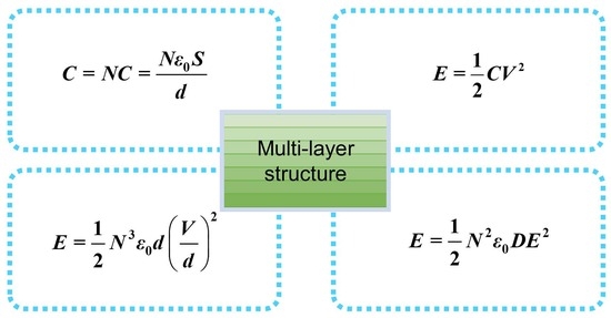
The structure of a TENG with multilayer dielectric materials is shown in Figure 1a. The dielectric material adopts a multi-layer structure. The good stretchability and charge trapping ability of SiO2 nanoparticle–elastomer composites are conducive to storing more charges during the charge excitation process, thus increasing the charge density of a TENG (Figure 1b). Triboelectric nanogenerators promote the rapid development of intelligent biomedicine [2,3]. Choosing composite materials with strong charge storage capacity as the charge storage layer to construct triboelectric materials is expected to resolve the contradiction between the overall improvement in their triboelectric charge density, stretchability, and biocompatibility. Each layer is a capacitor. The array charge storage layers consist of multilayer triboelectric materials. The total output voltage V′ is given by
The distribution of transferred charge is approximately uniform and the electric field inside the triboelectric material is uniform. The relevant electric field is defined as
Multilayer triboelectric materials are equivalent to multiple capacitors connected in parallel. The total capacitance C′ is
Substituting Equations (5) and (7) into Equation (2a), the total energy storage of a TENG (E′) is
Substituting Equation (6) into Equation (8), the energy storage is given by
The relationship between total maximum relative displacement (D) and single maximum relative displacement d is d = D/N. Substituting it into Equation (9), the energy storage can be written as
For energy storage devices, for example, batteries have a larger energy density than capacitors do, because energy is stored inside materials of multilayer charge and energy, whereas in capacitors, energy is stored at the surface of materials. For electric fields, a series capacitor can be used to increase the breakdown electric potential, and a shunt capacitor can be used to increase charge storage capacity. For a multi-layer structure like a monocharged electret, the maximum voltage of devices can increase times as a series capacitor, and the maximum charge of devices can increase times as a shunt capacitor; thus, the storage energy can increase times compared to a capacitor or even supercapacitor. In addition, the monocharged electret stores charge inside of the electret, whereas a multi-layer structure not only stores charge and energy in the bulk mode, but also output charge and energy during external short-circuit, mechanical triggering, chemical reaction, etc. According to this principle, we can design a rechargeable battery without an electrolyte with a higher energy density than a lithium ion battery. This new power cell also has fast charging and discharging like a capacitor.
For multilayer TENGs, Equations (8)–(10) show that the energy storage is affected by the number of layers, the distance between two electrodes, and the open-circuit voltage.
2.3. Electromechanical Coupling Coefficient of the TENG
To characterize the ability of a TENG to convert mechanical energy into electrical energy, we define the electromechanical coupling coefficient of a TENG, which can be expressed as
The maximum output energy per cycle Em can be obtained using the following equation [24]:
where QSC,max is the maximum value of transferred charge at short-circuit, VOC,max is the maximum open-circuit voltage, and V′max is the maximum achievable absolute voltage. The triboelectric charge is evenly distributed on the surface with negligible decay [35,36]. Thus, QSC,max, VOC,max, and V′max can be given as follows [24,37]:
where σ is the surface charge density and S is the electrode area. The effective thickness constant d0 is defined as the thickness of the dielectric (d) divided by its relative dielectric constant (εr). Substituting Equations (12)–(15) into Equation (11), the electromechanical coupling coefficient of the CS mode TENG is
where P = F/S is pressure.
3. Results and Discussion
Figure 2a shows that energy storage is obviously affected by the number of layers. Energy storage increases with the number of layers (N) and is proportional to the cube of N. Figure 2b shows that the energy storage is significantly affected by the open-circuit voltage (V) of a TENG. The energy storage increases with the open-circuit voltage. Energy is proportional to the square of the open-circuit voltage. Figure 2c shows that energy storage is significantly influenced by the distance (d) between two electrodes. When the open-circuit voltage is a fixed value, the energy storage increases as d decreases, and the energy storage is proportional to the countdown of d. When the electric field is constant, the energy storage increases as d increases and is linear with d.
The energy storage capacity of triboelectric materials can be improved through multilayer structure design [19,20,21,22]. The concept of maximizing energy storage by tuning the number of layers can also be realized through simple physical and chemical methods. Cui et al. constructed triboelectric materials with a multilayer structure by spin-coating [19]. Lai et al. integrated the spin-coating method and magnetron sputtering to study the transport and storage process of triboelectric charges in multilayer composites [20]. Xia et al. fabricated multilayer triboelectric composites with fillers using the repeated spin-coating technique [22]. Therefore, TENGs can obtain triboelectric materials with multilayer composite structures through repeated spin coating techniques, filling, and magnetron sputtering.
Internal charge injection via the polarization of piezoelectric material is an effective way to achieve high charge density in TENGs. Wang et al. increased the charge density of TENGs in a high vacuum from 660 μC m−2 to 1003 μC m−2 by integrating ferroelectric BT and PTFE [23]. Wang et al. achieved a high charge density of 1310 µCm−2 by spin-coating a layer of polymer material P(VDF-TrFE) onto the surface of PZT, which is 50 times the triboelectric density of PZT [38]. Wu et al. used carbon powder-polyvinylidene fluoride (CP-PVDF) composite films (filling concentration 0.18 wt‰) to increase the charge density of TENGs to 4.13 mCm−2 [39]. Wang et al. fabricated barium titanate (BTO) nanoparticle-filled polyvinylidene fluoride composite films with a charge density greater than 1.67 mCm−2 by spin-coating [40].
Taking a typical PZT/PTFE composite as an example, the schematic diagram of a TENG is shown in Figure 3a. The dielectric layer and top electrode are stacked face-to-face and generate opposite triboelectric charges through physical contact. The distance (x) between the dielectric layer and the top electrode varies with a constant mechanical force (F), resulting in the transfer of free electrons between the two electrodes. The electromechanical coupling coefficient represents the energy conversion efficiency of the piezoelectric material between electrical energy and mechanical energy [41].
Under a fixed pressure, the surface charge density of the PZT/PTFE composite TENG (σ) increased through the coupling of the triboelectric surface charge density σt and the piezoelectric polarization charge density on the top surface σp(z). The triboelectric surface charge density of PTFE (σt) in a TENG has a typical value of 50 μC/m2 [23]. The piezoelectric polarization charge density σp(z) can be simulated by using the COMSOL Multiphysics software. In our simulation, the composite structure is modeled with an array of charge generating units. The size of the single charge generating unit is 4 × 4 × 50 μm, which contains a PZT nanowire with a diameter of 2 μm and a length of 49 μm (Figure 3b). For the boundary condition, a uniform pressure of 1 MPa is applied on the top surface. The maximum values of short-circuit transferred charge (QSC,max), open-circuit voltage (VOC,max), and absolute voltage (V′max) are calculated using COMSOL. COMSOL provides an ideal model to understand the effect of the arrangement and morphology of piezoelectric materials on the surface charge density of composites [42,43]. Multilayer structures are used to study external charge injection in triboelectric materials. Our model describes charge injection inside triboelectric materials. The size of the PZT/PTFE composite film is 1 mm × 1 mm × 50 μm (Figure 3b).
Equation (16) can be used to calculate the conversion efficiency between mechanical and electrical energy in TENGs. Figure 3c shows that application of the piezoelectric material can increase k2 as additional piezoelectric charges are generated with each cycle. The electromechanical coupling coefficient of PZT/PTFE is higher than that of PTFE at an external pressure of 0.2 MPa to 10 MPa, as shown in Figure 3c. By integrating PTFE with PZT, the electromechanical coupling coefficient slowly decreases when the pressure varies between 0.2 MPa and 0.9 MPa and increases rapidly from 0.9 MPa to 10 MPa (Figure 3c). Under a pressure of 10 MPa, the electromechanical coupling coefficient of the PZT/PTFE composite TENG is two orders of magnitude larger than that of the PTFE TENG. The influence of effective thickness constant (d0) and air gap distance (x) on the electromechanical coupling coefficient is shown in Figure 3d. For a relatively small d0, k2 rapidly reaches its saturation value (xmax = 0.001 m). When d0 is more than 2.5 mm, k2 cannot be saturated, due to the charge transfer efficiency limitation by xmax/d0 on [44].
To further improve the electromechanical coupling coefficient, the structure of the PZT/PTFE film was optimized using the finite element method to generate more surface charges at the same pressure. The length and diameter of the nanowires as well as the effects of air breakdown and pressure on the surface charge density were investigated. Multiple layers are stacked using a simple repeated spin-coating method [19,20,21,22]. The surface charge density of the composites can be increased by changing the arrangement and morphology of the filler [20,21,22,38,40,45]. The influence of the arrangement and morphology of piezoelectric materials on the surface charge density of triboelectric composites was investigated using PZT nanowires as an example.
As shown in Figure 4a, the total displacement of the PZT/PTFE composite film (D) at a given pressure decreases with the length of the PZT nanowire from 5 μm to 49 μm. However, under the same conditions, the total displacement of the top surface of the PZT nanowire (D1) increases. When the bottom is fixed and a pressure of 1 MPa is uniformly applied to the top, the total displacement along the Z-axis increases. Therefore, the increased length decreases the total displacement of the PZT/PTFE composite film but increases the total displacement of the PZT nanowire tip. The high total displacement of the PZT nanowires corresponds to the application of high pressure to the tip of the PZT nanowires. The distance between the nanowire tip and the top electrode is short. As a result, increasing the length of the PZT nanowire leads to an increase in the charge density on the top electrode, as shown in Figure 4b.
Figure 4c shows the air breakdown voltage (Vb) in the atmosphere and the gap voltage (Vgap) between contact surfaces with different surface charge densities. Vb is given by Paschen’s law [46]:
where B is related to the excitation and ionization energies, p is the gas pressure, x is the gap distance, A is the saturation ionization in the gas, and γ is the secondary ionization coefficient. For a given diameter of 1.0 μm, the length of the PZT nanowire increases from 5 μm to 49 μm, corresponding to an increase in surface charge density from 50.3 μC/m2 to 114.8 μC/m2. As shown in Figure 4c, the gap voltage between the contact surfaces is smaller than the air breakdown voltage when the surface charge density σ is 114.8 μC/m2. The maximum output power is not limited by air breakdown. The corresponding V-Q curves are calculated, as shown in Figure 4d. With a PZT length of 49 μm, the Em generated by the PZT/PTFE composite TENG is up to 0.29 J/m2, which is five times that of the PTFE TENG.
To further optimize the structure of PZT/PTFE composite film, the performance of the TENG is studied using various diameters of PZT nanowire, as shown in Figure 5. The total displacement of the PZT/PTFE composite film (D) and the total displacement of the top surface of the PZT nanowire (D1) decline significantly when the diameter varies from 0.2 μm to 1.0 μm and decline slightly when the diameter is larger than 1.0 μm (Figure 5a). The PZT/PTFE composite can generate a maximum surface charge density of 145.6 μC/m2 taking into account the trade-off between the decreased piezoelectric charge density and the increased area of the top surface of the PZT nanowire (Figure 5b). For TENGs with a surface charge density of 145.6 μC/m2, the gap voltage between the triboelectric surfaces is slightly smaller than the air breakdown voltage (Figure 5c). The V-Q curves of TENGs with different surface charge density are shown in Figure 5d. The maximum Em value is 0.48 J/m2, which is eight times higher than that of PTFE TENG.
In addition to improving the electromechanical structure of the PZT/PTFE composite, the surface charge density can also be increased by increasing the pressure (Figure 6a). In Figure 3, Figure 4, Figure 5 and Figure 6, the signal is a hybrid signal of PTFE-PZT. We use the piezoelectric polarization of PZT to enhance charge storage in this work. PZT produces an internal electric field to drive charge injection and increase charge density, thus achieving high-energy-density materials. The surface charge density reaches the maximum value at air breakdown. The maximum surface charge density of a TENG (σTENG) can be given by [23]
Researchers showed that the surface charge density of a TENG in vacuum can be further increased without air breakdown. Under vacuum, the maximum σTENG is limited by the dielectric breakdown (σdielectric_breakdown). The σdielectric_breakdown can be obtained from [23]
where Ebreakdown is the breakdown electric field of dielectric materials. Because the breakdown electric field and relative permittivity of PZT are higher than those of PTFE, the σdielectric_breakdown of the PZT/PTFE composite film can be higher than that of the PTFE film. The σdielectric_breakdown of the PTFE film is calculated to be 1062 μC/m2, which is less than 95.65 mC/m2 (under a pressure of 1 GPa).
With consideration of the presence of dielectric breakdown, the maximum surface charge density under a pressure of 10 MPa is 1006 μC/m2, which is not far from the σdielectric_breakdown of 1062 μC/m2. The V-Q curves with various surface charge densities are plotted in Figure 6b. Under a pressure of 10 MPa, the Em and k2 of the PZT/PTFE composite TENG are 380 times higher than that of the PTFE TENG. It is worth emphasizing that the surface charge density of a TENG can be further increased by using a dielectric material with a high dielectric constant and a high dielectric breakdown voltage.
Considering the existence of dielectric breakdown, the maximum surface charge density at a pressure of 10 MPa is 1006 μC/m2, which is not far from the σdielectric_breakdown of 1062 μC/m2. The V-Q curves with different surface charge densities are shown in Figure 6b. Under the pressure of 10 MPa, Em and k2 of the PZT/PTFE composite TENG are 380 times those of the PTFE TENG. Importantly, the surface charge density of TENGs can be further increased by using dielectric materials with a high dielectric constant and high dielectric breakdown voltage.
4. Conclusions
A method for evaluating the charge storage properties of triboelectric materials has been developed. The maximum energy density of the triboelectric material is derived from the determined charge Q and the open-circuit voltage V. Based on the maximum energy density and considering the material structure, E′ is derived to evaluate triboelectric material designs. The total energy storage of triboelectric materials with multilayer structures is simulated using COMSOL and shows the maximum value of E′ for multilayer structures. The evaluation method provides a new way for the design of high-performance triboelectric materials.
By integrating PTFE with PZT, a TENG with a higher electromechanical coupling coefficient is developed. This TENG structure generates more surface charge at the same pressure. Due to the compensation effect of the piezoelectric charge, the electromechanical coupling coefficient of the TENG is greatly increased under high pressure. By optimizing the electromechanical structure of the PZT/PTFE composite, the surface charge density increases from 50 C/m2 to 145.6 C/m2 and further to 1006 C/m2 in vacuum. Under a pressure of 10 MPa, the output energy density of the PZT/PTFE composite TENG is 380 times that of the PTFE TENG.
There are two types of charge injection for the charge storage layer of TENGs: external and internal electric field modes. External-field-driven charge injection is a typical mode in electret, triboelectric materials, and high-energy-density charge storage materials. Charges can be injected using electrodes of electret, TENGs, and energy devices.
Author Contributions
X.C.: Conceptualization, Methodology, Formal Analysis, Data Curation, Writing—Original Draft, Validation; Y.Z. (Yaming Zhang): Methodology, Formal Analysis, Data Curation, Writing—Original Draft; Y.Z. (Yan Zhang): Conceptualization, Methodology, Data Curation, Supervision, Formal Analysis, Writing—Original Draft, Writing—Review and Editing. All authors have read and agreed to the published version of the manuscript.
Funding
This research was funded by the Major Program of the National Natural Science Foundation of China (Grant No. 52192612, 52192610), the Key Program of the National Natural Science Foundation of China (Grant No. U22A2077), and the University of Electronic Science and Technology of China (Grant No. ZYGX2021YGCX001).
Data Availability Statement
Data are contained within the article.
Conflicts of Interest
The authors declare no conflict of interest.
References
- Cheng, T.; Shao, J.; Wang, Z.L. Triboelectric nanogenerators. Nat. Rev. Methods Primers 2023, 3, 39. [Google Scholar] [CrossRef]
- Won, S.M.; Cai, L.; Gutruf, P.; Rogers, J.A. Wireless and battery-free technologies for neuroengineering. Nat. Biomed. Eng. 2023, 7, 405–423. [Google Scholar] [CrossRef]
- Zheng, Q.; Tang, Q.; Wang, Z.L.; Li, Z. Self-powered cardiovascular electronic devices and systems. Nat. Rev. Cardiol. 2021, 18, 7–21. [Google Scholar] [CrossRef]
- Xu, W.; Zheng, H.; Liu, Y.; Zhou, X.; Zhang, C.; Song, Y.; Deng, X.; Leung, M.; Yang, Z.; Xu, R.X.; et al. A droplet-based electricity generator with high instantaneous power density. Nature 2020, 578, 392–396. [Google Scholar] [CrossRef]
- Zhang, Y.; Lu, Q.; He, J.; Huo, Z.; Zhou, R.; Han, X.; Jia, M.; Pan, C.; Wang, Z.L.; Zhai, J. Localizing strain via micro-cage structure for stretchable pressure sensor arrays with ultralow spatial crosstalk. Nat. Commun. 2023, 14, 1252. [Google Scholar] [CrossRef]
- Qu, X.; Liu, Z.; Tan, P.; Wang, C.; Liu, Y.; Feng, H.; Luo, D.; Li, Z.; Wang, Z.L. Artificial tactile perception smart finger for material identification based on triboelectric sensing. Sci. Adv. 2022, 8, eabq2521. [Google Scholar] [CrossRef]
- Hinchet, R.; Yoon, H.-J.; Ryu, H.; Kim, M.-K.; Choi, E.-K.; Kim, D.-S.; Kim, S.-W. Transcutaneous ultrasound energy harvesting using capacitive triboelectric technology. Science 2019, 365, 491–494. [Google Scholar] [CrossRef]
- Choi, D.; Lee, Y.; Lin, Z.-H.; Cho, S.; Kim, M.; Ao, C.K.; Soh, S.; Sohn, C.; Jeong, C.K.; Lee, J.; et al. Recent Advances in Triboelectric Nanogenerators: From Technological Progress to Commercial Applications. ACS Nano 2023, 17, 11087–11219. [Google Scholar] [CrossRef]
- Zhao, Z.; Dai, Y.; Liu, D.; Zhou, L.; Li, S.; Wang, Z.L.; Wang, J. Rationally patterned electrode of direct-current triboelectric nanogenerators for ultrahigh effective surface charge density. Nat. Commun. 2020, 11, 6186. [Google Scholar] [CrossRef]
- Liu, D.; Gao, Y.; Zhou, L.; Wang, J.; Wang, Z.L. Recent advances in high-performance triboelectric nanogenerators. Nano Res. 2023, 1–20. [Google Scholar] [CrossRef]
- Li, W.; Torres, D.; Díaz, R.; Wang, Z.; Wu, C.; Wang, C.; Lin Wang, Z.; Sepúlveda, N. Nanogenerator-based dual-functional and self-powered thin patch loudspeaker or microphone for flexible electronics. Nat. Commun. 2017, 8, 15310. [Google Scholar] [CrossRef]
- Wang, J.; Li, S.; Yi, F.; Zi, Y.; Lin, J.; Wang, X.; Xu, Y.; Wang, Z.L. Sustainably powering wearable electronics solely by biomechanical energy. Nat. Commun. 2016, 7, 12744. [Google Scholar] [CrossRef]
- Liu, J.X.; Liu, G.; Guo, Z.H.; Hu, W.; Zhang, C.; Pu, X. Electret elastomer-based stretchable triboelectric nanogenerators with autonomously managed power supplies for self-charging systems. Chem. Eng. J. 2023, 462, 142167. [Google Scholar] [CrossRef]
- Zhang, S.; Wang, Y.; Yao, X.; Le Floch, P.; Yang, X.; Liu, J.; Suo, Z. Stretchable Electrets: Nanoparticle–Elastomer Composites. Nano Lett. 2020, 20, 4580–4587. [Google Scholar] [CrossRef]
- Xu, L.; Bu, T.Z.; Yang, X.D.; Zhang, C.; Wang, Z.L. Ultrahigh charge density realized by charge pumping at ambient conditions for triboelectric nanogenerators. Nano Energy 2018, 49, 625–633. [Google Scholar] [CrossRef]
- Liu, W.; Wang, Z.; Wang, G.; Liu, G.; Chen, J.; Pu, X.; Xi, Y.; Wang, X.; Guo, H.; Hu, C.; et al. Integrated charge excitation triboelectric nanogenerator. Nat. Commun. 2019, 10, 1426. [Google Scholar] [CrossRef]
- Cheng, L.; Xu, Q.; Zheng, Y.; Jia, X.; Qin, Y. A self-improving triboelectric nanogenerator with improved charge density and increased charge accumulation speed. Nat. Commun. 2018, 9, 3773. [Google Scholar] [CrossRef]
- Xie, X.; Chen, X.; Zhao, C.; Liu, Y.; Sun, X.; Zhao, C.; Wen, Z. Intermediate layer for enhanced triboelectric nanogenerator. Nano Energy 2021, 79, 105439. [Google Scholar] [CrossRef]
- Cui, N.; Gu, L.; Lei, Y.; Liu, J.; Qin, Y.; Ma, X.; Hao, Y.; Wang, Z.L. Dynamic Behavior of the Triboelectric Charges and Structural Optimization of the Friction Layer for a Triboelectric Nanogenerator. ACS Nano 2016, 10, 6131–6138. [Google Scholar] [CrossRef]
- Lai, M.; Du, B.; Guo, H.; Xi, Y.; Yang, H.; Hu, C.; Wang, J.; Wang, Z.L. Enhancing the Output Charge Density of TENG via Building Longitudinal Paths of Electrostatic Charges in the Contacting Layers. ACS Appl. Mater. Interfaces 2018, 10, 2158–2165. [Google Scholar] [CrossRef]
- Gao, S.; Wang, R.; Ma, C.; Chen, Z.; Wang, Y.; Wu, M.; Tang, Z.; Bao, N.; Ding, D.; Wu, W.; et al. Wearable high-dielectric-constant polymers with core-shell liquid metal inclusions for biomechanical energy harvesting and a self-powered user interface. J. Mater. Chem. A 2019, 7, 7109–7117. [Google Scholar] [CrossRef]
- Xia, X.; Chen, J.; Liu, G.; Javed, M.S.; Wang, X.; Hu, C. Aligning graphene sheets in PDMS for improving output performance of triboelectric nanogenerator. Carbon 2017, 111, 569–576. [Google Scholar] [CrossRef]
- Wang, J.; Wu, C.; Dai, Y.; Zhao, Z.; Wang, A.; Zhang, T.; Wang, Z.L. Achieving ultrahigh triboelectric charge density for efficient energy harvesting. Nat. Commun. 2017, 8, 88. [Google Scholar] [CrossRef] [PubMed]
- Zi, Y.; Niu, S.; Wang, J.; Wen, Z.; Tang, W.; Wang, Z.L. Standards and figure-of-merits for quantifying the performance of triboelectric nanogenerators. Nat. Commun. 2015, 6, 8376. [Google Scholar] [CrossRef]
- Wang, Z.; Cheng, L.; Zheng, Y.; Qin, Y.; Wang, Z.L. Enhancing the performance of triboelectric nanogenerator through prior-charge injection and its application on self-powered anticorrosion. Nano Energy 2014, 10, 37–43. [Google Scholar] [CrossRef]
- Wang, S.; Xie, Y.; Niu, S.; Lin, L.; Liu, C.; Zhou, Y.S.; Wang, Z.L. Maximum surface charge density for triboelectric nanogenerators achieved by ionized-air injection: Methodology and theoretical understanding. Adv. Mater. 2014, 26, 6720–6728. [Google Scholar] [CrossRef]
- Wang, S.; Zi, Y.; Zhou, Y.S.; Li, S.; Fan, F.; Lin, L.; Wang, Z.L. Molecular surface functionalization to enhance the power output of triboelectric nanogenerators. J. Mater. Chem. A 2016, 4, 3728–3734. [Google Scholar] [CrossRef]
- Jeong, C.K.; Baek, K.M.; Niu, S.; Nam, T.W.; Hur, Y.H.; Park, D.Y.; Hwang, G.T.; Byun, M.; Wang, Z.L.; Jung, Y.S.; et al. Topographically-designed triboelectric nanogenerator via block copolymer self-assembly. Nano Lett. 2014, 14, 7031–7038. [Google Scholar] [CrossRef]
- Wang, S.; Lin, L.; Wang, Z.L. Nanoscale triboelectric-effect-enabled energy conversion for sustainably powering portable electronics. Nano Lett. 2012, 12, 6339–6346. [Google Scholar] [CrossRef]
- Tang, W.; Meng, B.; Zhang, H.X. Investigation of power generation based on stacked triboelectric nanogenerator. Nano Energy 2013, 2, 1164–1171. [Google Scholar] [CrossRef]
- Kim, S.; Gupta, M.K.; Lee, K.Y.; Sohn, A.; Kim, T.Y.; Shin, K.S.; Kim, D.; Kim, S.K.; Lee, K.H.; Shin, H.J.; et al. Transparent flexible graphene triboelectric nanogenerators. Adv. Mater. 2014, 26, 3918–3925. [Google Scholar] [CrossRef] [PubMed]
- Lee, K.Y.; Chun, J.; Lee, J.H.; Kim, K.N.; Kang, N.R.; Kim, J.Y.; Kim, M.H.; Shin, K.S.; Gupta, M.K.; Baik, J.M.; et al. Hydrophobic sponge structure-based triboelectric nanogenerator. Adv. Mater. 2014, 26, 5037–5042. [Google Scholar] [CrossRef] [PubMed]
- Mariello, M. Recent Advances on Hybrid Piezo-Triboelectric Bio-Nanogenerators: Materials, Architectures and Circuitry. Nanoenergy Adv. 2022, 2, 64–109. [Google Scholar] [CrossRef]
- Wang, S.; Tong, W.; Li, Y.; Zhang, P.; Liu, Y.; Chen, Y.; Zhang, Y. Contributions of piezoelectricity and triboelectricity to a hydroxyapatite/PVDF–HFP fiber-film nanogenerator. Nano Energy 2023, 105, 108026. [Google Scholar] [CrossRef]
- Lee, L.-H. Dual mechanism for metal-polymer contact electrification. J. Electrost. 1994, 32, 1–29. [Google Scholar] [CrossRef]
- Saurenbach, F.; Wollmann, D.; Terris, B.D.; Diaz, A.F. Force microscopy of ion-containing polymer surfaces: Morphology and charge structure. Langmuir 1992, 8, 1199–1203. [Google Scholar] [CrossRef]
- Niu, S.; Wang, S.; Lin, L.; Liu, Y.; Zhou, Y.S.; Hu, Y.; Wang, Z.L. Theoretical study of contact-mode triboelectric nanogenerators as an effective power source. Energy Environ. Sci. 2013, 6, 3576–3583. [Google Scholar] [CrossRef]
- Wang, J.; Li, G.; Xu, S.; Wu, H.; Fu, S.; Shan, C.; He, W.; Zhao, Q.; Li, K.; Hu, C. Remarkably Enhanced Charge Density of Inorganic Material Via Regulating Contact Barrier Difference and Charge Trapping for Triboelectric Nanogenerator. Adv. Funct. Mater. 2023, 2304221. [Google Scholar] [CrossRef]
- Wu, H.; Wang, J.; He, W.; Shan, C.; Fu, S.; Li, G.; Zhao, Q.; Liu, W.; Hu, C. Ultrahigh output charge density achieved by charge trapping failure of dielectric polymers. Energy Environ. Sci. 2023, 16, 2274–2283. [Google Scholar] [CrossRef]
- Wang, J.; Wu, H.; Wang, Z.; He, W.; Shan, C.; Fu, S.; Du, Y.; Liu, H.; Hu, C. An Ultrafast Self-Polarization Effect in Barium Titanate Filled Poly(Vinylidene Fluoride) Composite Film Enabled by Self-Charge Excitation Triboelectric Nanogenerator. Adv. Funct. Mater. 2022, 32, 2204322. [Google Scholar] [CrossRef]
- Qi, Y.; McAlpine, M.C. Nanotechnology-enabled flexible and biocompatible energy harvesting. Energy Environ. Sci. 2010, 3, 1275–1285. [Google Scholar] [CrossRef]
- Hinchet, R.; Lee, S.; Ardila, G.; Montès, L.; Mouis, M.; Wang, Z.L. Performance Optimization of Vertical Nanowire-based Piezoelectric Nanogenerators. Adv. Funct. Mater. 2014, 24, 971–977. [Google Scholar] [CrossRef]
- Cui, X.; Ni, X.; Zhang, Y. Theoretical study of output of piezoelectric nanogenerator based on composite of PZT nanowires and polymers. J. Alloys Compd. 2016, 675, 306–310. [Google Scholar] [CrossRef]
- Niu, S.; Liu, Y.; Wang, S.; Lin, L.; Zhou, Y.S.; Hu, Y.; Wang, Z.L. Theory of sliding-mode triboelectric nanogenerators. Adv. Mater. 2013, 25, 6184–6193. [Google Scholar] [CrossRef] [PubMed]
- Hu, C.; Cheng, L.; Wang, Z.; Zheng, Y.; Bai, S.; Qin, Y. A Transparent Antipeep Piezoelectric Nanogenerator to Harvest Tapping Energy on Screen. Small 2016, 12, 1315–1321. [Google Scholar] [CrossRef]
- Husain, E.; Nema, R.S. Analysis of Paschen Curves for air, N2 and SF6 Using the Townsend Breakdown Equation. ITEI 1982, 4, 350–353. [Google Scholar] [CrossRef]
Figure 1.
Design of multilayer structures for dielectric materials. (a) TENG with multilayer-structured dielectric materials. (b) The fundamental scheme to improving the charge density of TENG by optimizing materials and charge excitation. Arrows denote the polarization direction.
Figure 1.
Design of multilayer structures for dielectric materials. (a) TENG with multilayer-structured dielectric materials. (b) The fundamental scheme to improving the charge density of TENG by optimizing materials and charge excitation. Arrows denote the polarization direction.

Figure 2.
The energy storage of TENG changes with (a) the number of TENGs. The inset shows the TENG structure. (b) The output potential of TENG. (c) The distance between the charged surfaces of TENG.
Figure 2.
The energy storage of TENG changes with (a) the number of TENGs. The inset shows the TENG structure. (b) The output potential of TENG. (c) The distance between the charged surfaces of TENG.

Figure 3.
K2 for different TENG structures. (a) Schematic illustration of the PZT/PTFE TENG and (b) structure of the TENG utilized in this calculation. (c) The K2 for PTFE TENG and PZT/PTFE composite TENG calculated using analytical formulas. (d) The K2 of the PTFE TENG with various d0.
Figure 3.
K2 for different TENG structures. (a) Schematic illustration of the PZT/PTFE TENG and (b) structure of the TENG utilized in this calculation. (c) The K2 for PTFE TENG and PZT/PTFE composite TENG calculated using analytical formulas. (d) The K2 of the PTFE TENG with various d0.

Figure 4.
Output performance of CS TENG with various lengths of the PZT nanowire. (a) The total displacement of PTFE/PZT composite (D) and PZT nanowire (D1), (b) surface charge density as a function of the length of the PZT nanowire at constant diameter of 1 μm. (c) Air breakdown voltage at the pressure of the gas and gap voltage of TENG, and (d) the V-Q plot of CS TENG with various charge densities. The thickness of PTFE/PZT composite film is 50 μm.

Figure 5.
Output performance of CS mode TENG using various diameters of the PZT nanowire. (a) The total displacement of PTFE/PZT composite (D) and PZT nanowire (D1), and (b) charge density of the TENG with various diameters. (c) Air breakdown voltage at the pressure of the gas and gap voltage of TENG, and (d) the V-Q plot of CS-mode TENG with various charge densities.

Figure 6.
Output performance of CS-mode TENG in the vacuum. (a) Charge density of TENG with various pressures. (b) The V-Q plot of CS-mode TENG with various charge densities.
Figure 6.
Output performance of CS-mode TENG in the vacuum. (a) Charge density of TENG with various pressures. (b) The V-Q plot of CS-mode TENG with various charge densities.

Disclaimer/Publisher’s Note: The statements, opinions and data contained in all publications are solely those of the individual author(s) and contributor(s) and not of MDPI and/or the editor(s). MDPI and/or the editor(s) disclaim responsibility for any injury to people or property resulting from any ideas, methods, instructions or products referred to in the content. |
© 2023 by the authors. Licensee MDPI, Basel, Switzerland. This article is an open access article distributed under the terms and conditions of the Creative Commons Attribution (CC BY) license (https://creativecommons.org/licenses/by/4.0/).
Share and Cite
MDPI and ACS Style
Cui, X.; Zhang, Y.; Zhang, Y. Multi-Charge Storage Layer Model of High-Charge-Density Triboelectric Nanogenerator. Nanoenergy Adv. 2023, 3, 247-258. https://doi.org/10.3390/nanoenergyadv3030013
AMA Style
Cui X, Zhang Y, Zhang Y. Multi-Charge Storage Layer Model of High-Charge-Density Triboelectric Nanogenerator. Nanoenergy Advances. 2023; 3(3):247-258. https://doi.org/10.3390/nanoenergyadv3030013
Chicago/Turabian StyleCui, Xin, Yaming Zhang, and Yan Zhang. 2023. "Multi-Charge Storage Layer Model of High-Charge-Density Triboelectric Nanogenerator" Nanoenergy Advances 3, no. 3: 247-258. https://doi.org/10.3390/nanoenergyadv3030013