A New Moment-Resisting Glulam Beam-End Connection Utilizing Mechanically Fastened Steel Rods—An Experimental Study


Department of Civil Engineering, Lakehead University, 955 Oliver Road, Thunder Bay, ON P7B 5E1, Canada
*
Author to whom correspondence should be addressed.
Appl. Mech. 2024, 5(2), 260-279; https://doi.org/10.3390/applmech5020016
Submission received: 1 February 2024
/
Revised: 12 March 2024
/
Accepted: 25 March 2024
/
Published: 29 March 2024
(This article belongs to the Special Issue Early Career Scientists’ (ECS) Contributions to Applied Mechanics (2nd Edition))
Abstract
:A new moment-resisting mass timber connection was designed based on the principles of force equilibrium in applied mechanics. The connection configuration utilizing two mechanically fastened threaded steel rods embedded into the end of a glulam beam section was experimentally investigated in this study. A gradually increasing transverse load was applied to the free end of a cantilevered beam, causing a bending moment on the beam-end connection until failure. Four different connection configurations were examined, each replicated twice to verify results. The beam connection parameters investigated were rod anchorage length (200 and 250 mm) and square washer size (38.1 and 50.8 mm). Test results show that increasing the washer size increased the connection bending strength by increments more significantly than those due to increasing the rod anchorage length. However, the connection configurations with the smaller-size washer, which failed mainly due to wood crushing under the washer, had higher ductility ratios than those with the larger-size washer, which failed due to steel rod yielding. In a real-life scenario, a structural element such as a glulam beam is usually loaded to approximately 50% to 70% of its design capacity, considering a reasonable margin of safety. The study estimates a maximum possible bending moment utilization factor for the strongest connection configuration that ranged between 34% and 48% compared to the maximum moment resistance of a supported glulam beam spanning an average length of 4.0 m to 6.0 m (a common span length in framed timber buildings) and has a cross-section size same as the one utilized in this study. This utilization factor is quite large for a timber connection, and thus, confirms a considerable moment-resisting capability of the new configuration developed in this study.
1. Introduction
The current version of the National Building Code of Canada (NBCC 2020) has increased the height restriction of buildings primarily made of wood to twelve storeys (42 m above ground) [1]. As such, taller wood buildings are expected to undergo loading beyond the capacity of available sawn timber sections. This highlights the demand for larger glulam structural components as they can sustain considerably larger loads when compared to commercially available sawn timber sections. Currently, there is a lack of design guidance for moment-resisting timber beam-to-column connections, a key requirement for taller buildings which are expected to be susceptible to considerable lateral loads combined with significant gravity loads. In this context, the primary concern of using timber moment-resisting frames is its capability to resist moments without exhibiting brittle failures at their connections, such as wood splitting and row shear.
Using metal connectors promotes mass timber connections to behave more ductile by providing a source of energy dissipation and designing the connection to fail in the steel components instead of the wood [2,3]. Nevertheless, brittle failure can still be developed before the connection exhibits any possible ductile behaviour [4]. An additional consideration for optimizing glulam elements for practical construction use is their behaviour as rotationally restrained elements in framed timber structures. The behaviour of timber connections used in framed structures and subjected to axial loads was investigated [5]. A few studies [6,7] have been undertaken to investigate the moment resistance of timber connections as part of a framework, with other studies focused on the lateral resistance of timber frames [8]. Mass timber frames with semi-rigid beam-to-column connections can provide a sufficient load-carrying mechanism for both gravity and lateral loads for timber buildings. Beam–column moment-resisting connections with adequate ductility are crucial to ensure robustness and energy dissipation [9]. Experimental investigations on the glulam beam–column moment-resisting connections using self-tapping screws as fasteners have been conducted in a relatively recent study by [10]. The self-tapping screws or threaded rods with sufficient lengths provide an alternative connecting mechanism to join mass timber sections, allowing higher strength and stiffness connections in timber buildings [10].
A strong contender for a more ductile moment-resisting timber connection is to use glued-in threaded steel rods. Glued-in threaded steel rods have been used and experimentally tested since the late 1980s; however, no consistent design procedures exist for their applications [11,12]. Some design approaches and code models have been published. However, considerable discrepancies and partial contradictions exist between the different design models in the literature [13]. Experimental results show that threaded steel rods can reduce brittle failures from being developed in wood sections [14]. As such connections are composed of several materials, e.g., wood, steel, and adhesive, they are considered hybrid. The interaction between different materials in a connection configuration makes it more complex to design such a connection with several variables that need to be considered. In addition, predicting the failure modes of glued-in rod connections and their ultimate strength is challenging [15]. Important factors that have been found to affect the connection strength are rod anchorage length, the size of the hole compared to the rod diameter, the type of adhesive used, and wood species [13,16].
Steel rods can be epoxied into one member (e.g., beam) and secured with a nut and washer to the other member (e.g., column). Alternatively, the rod can be glued into two members, making the required connection [17]. A critical issue with connections composed of glued-in rods in both members is that the connection must be made on-site, and this has been shown to carry a high risk of being improperly bonded since the effectiveness of the grouting operation cannot be visually checked [18]. Therefore, it is highly recommended that the gluing process be done in a controlled environment where skilled workers can check their work and ensure a proper bond.
Alternatively, mechanically fastened steel rods can be more feasible and practical. Fastening can be done by preparing a small hole on the side of the timber beam to meet the end of the embedded steel rod, and then, a nut and a washer can be inserted to fasten the steel rod mechanically. Once the beam is connected, a small wood plug can be glued into the side hole, covering the nut and washer, providing a fully concealed connection like the glued-in rod connection. Such a connection can also be easily assembled in the field, eliminating the possibility of bond failure in the glued-in rods constructed in the field.
A prior study was conducted by Hubbard and Salem [19] on a single-threaded steel rod mechanically fastened into a glulam beam section tested under direct tension. The parameters investigated were rod anchorage length and washer size. Nine different connection configurations were tested, and the results provided insight into the modes of failure that could occur depending on the parameters of each configuration. According to the said study, it has been noticed that utilizing a shorter-anchorage length rod with a larger-size washer in the connection configuration promoted a wood splitting failure, which was unpredictable and hard to allow for any trend observation in the obtained results for the connection configurations that failed due to this failure mode.
In that study, it was concluded that having a rod anchorage length to washer size ratio of 4:1 resulted in a rod pull-out failure. It was also observed that the rod pull-out failure had the most predictable results and a consistent trend that could allow the connection to be designed for the steel rod to yield before the brittle rod pull-out failure occurred. A higher rod anchorage length to washer size ratio promoted a connection failure where the wood was crushed under the washer [19]. The results of such failure were almost as predictable as that of the rod pull-out failure. However, the wood crushing failure was considered a ductile failure until the final connection failure occurred due to either rod pull-out or wood splitting [19].
This paper presents the results of an experimental study undertaken to evaluate the behaviour of a new glulam beam-end moment-resisting connection that utilized two mechanically fastened threaded steel rods. The experimental program consisted of eight full-size beam-end connections subjected to gradually increased loading until failure. Test variables investigated in this study were rod anchorage length and square washer size. Each test assembly consisted of a cantilever glulam beam connected to a sturdy steel supporting column via two steel rods that were mechanically fastened and symmetrically placed within the depth of the beam section. Using a sturdy steel supporting column instead of a glulam column guaranteed the failure to occur solely in the wooden beam section at the connection. Accordingly, the isolation of the failure to the beam section allows for the two parameters (i.e., rod anchorage length and washer size) to be fairly studied and analyzed before adding another component that could make things more complex to comprehend.
The ultimate objective of this study is to develop a simple-to-design and easy-to-fabricate glulam beam-end connection configuration with sufficient moment-resisting capacity to be effectively utilized in mass timber-framed buildings. Unlike glued-in rod connections, the novelty of the newly developed connection configurations is their ability to be assembled on-site without challenging the quality control of the assembly.
2. Experimental Program
Four different connection configurations utilizing two mechanically fastened steel rods in glulam sections were experimentally examined, with each test assembly tested twice (i.e., A and B) to verify results. Using the collected load-displacement data, the strength and stiffness of the connections were calculated, and the connection failure modes were observed and documented.
2.1. Materials
2.1.1. Glulam Beams
The 1500 mm long glulam beams having cross-sectional dimensions of 137 mm × 318 mm used in the test assemblies were made of Spruce-Pine-Fir (S-P-F), comprised of 90% (Picea mariana), the black spruce, a North American species of spruce tree in the pine family [20]. The beam sections were manufactured to meet the 24F-ES/NPG stress grade with architectural appearance grade and have a wood density of 560 kg/m3 [20]. The individual lamina stocks used to build up the beam sections measured approximately 25 mm × 50 mm. The lamina stocks were finger-jointed at their ends and face and side-glued in horizontal and vertical layers. The actual dimensions of the beam sections used in the test specimens were 135 × 314 × 1500 mm, slightly smaller than the original due to wood shrinkage that took place while the beam sections were stored indoors for more than three months before being tested. The average moisture content of the glulam sections measured right before experiments was approximately 10%. The principle mechanical design properties of the glulam sections are listed in Table 1 as given in the Canadian Construction Materials Centre (CCMC) Evaluation report 13216-R [20].
2.1.2. Threaded Rods
The threaded rods used in the experiments had a diameter of 19.05 mm, length of 910 mm, and stress grade of SAE J429-Grade 2, the common steel rod grade used in wood construction. Using a band saw, the rods were cut into pieces 470 and 520 mm long, used in the test assemblies with 200 mm and 250 mm rod anchorage lengths, respectively. The remaining cut-off rod segments were prepared, used as tension coupons, and tested to verify the stress grade of the rods. The average yield strength of the rods was recorded at 400 MPa, confirming the rods’ stress grade.
2.1.3. Washers
The washers used for the experiments were fabricated from a 12.7 mm thick steel flat bar with a stress grade of 300 W (average yield strength of 300 MPa), as specified by CSA G40.20-04/G40.21-13 [21]. Washers were fabricated in two sizes (i.e., 38.1 × 38.1 mm and 50.8 × 50.8 mm). A hole of 20.6 mm diameter was drilled in the centre of each washer.
2.2. Test Assembly Details and Fabrication Process
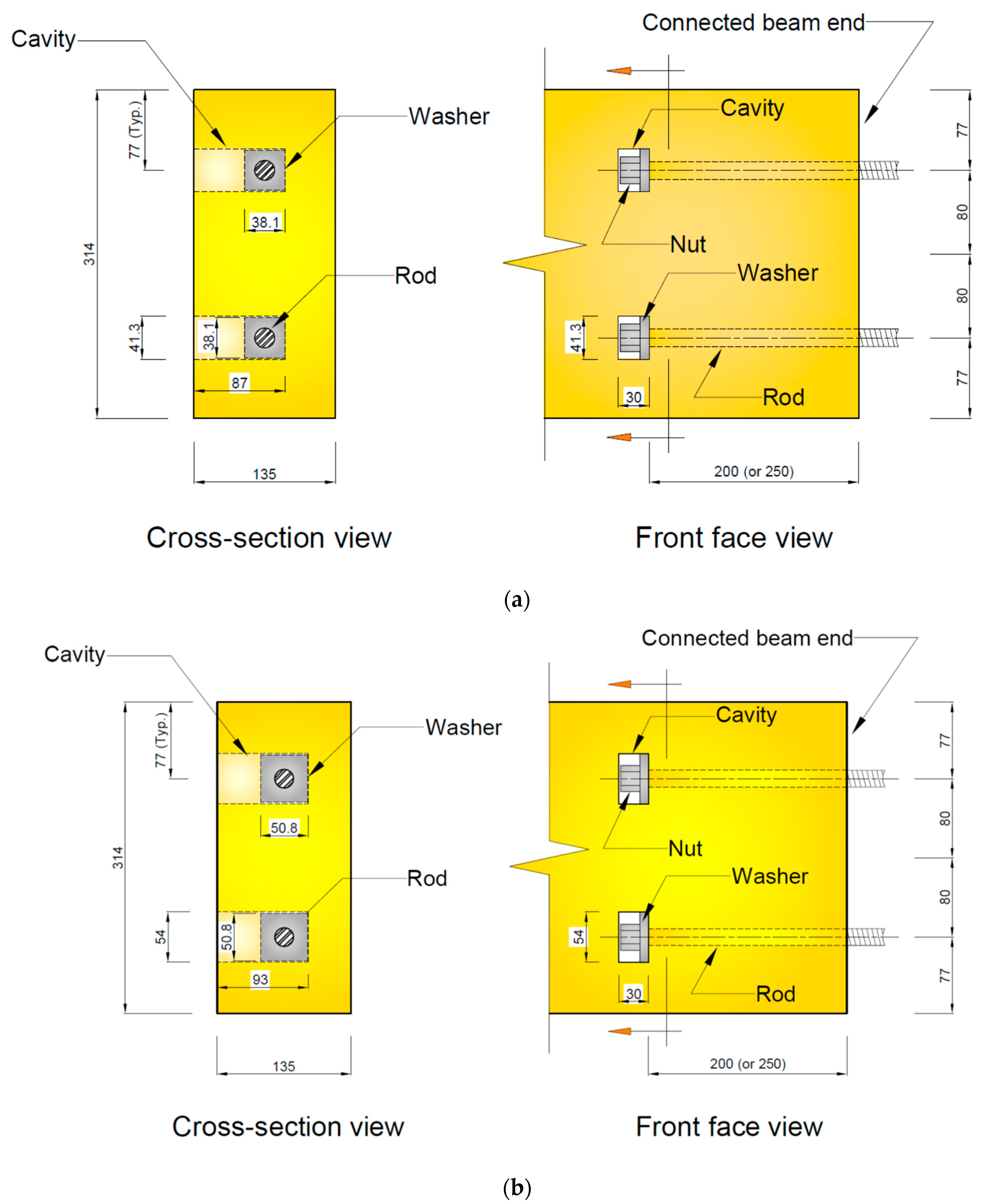
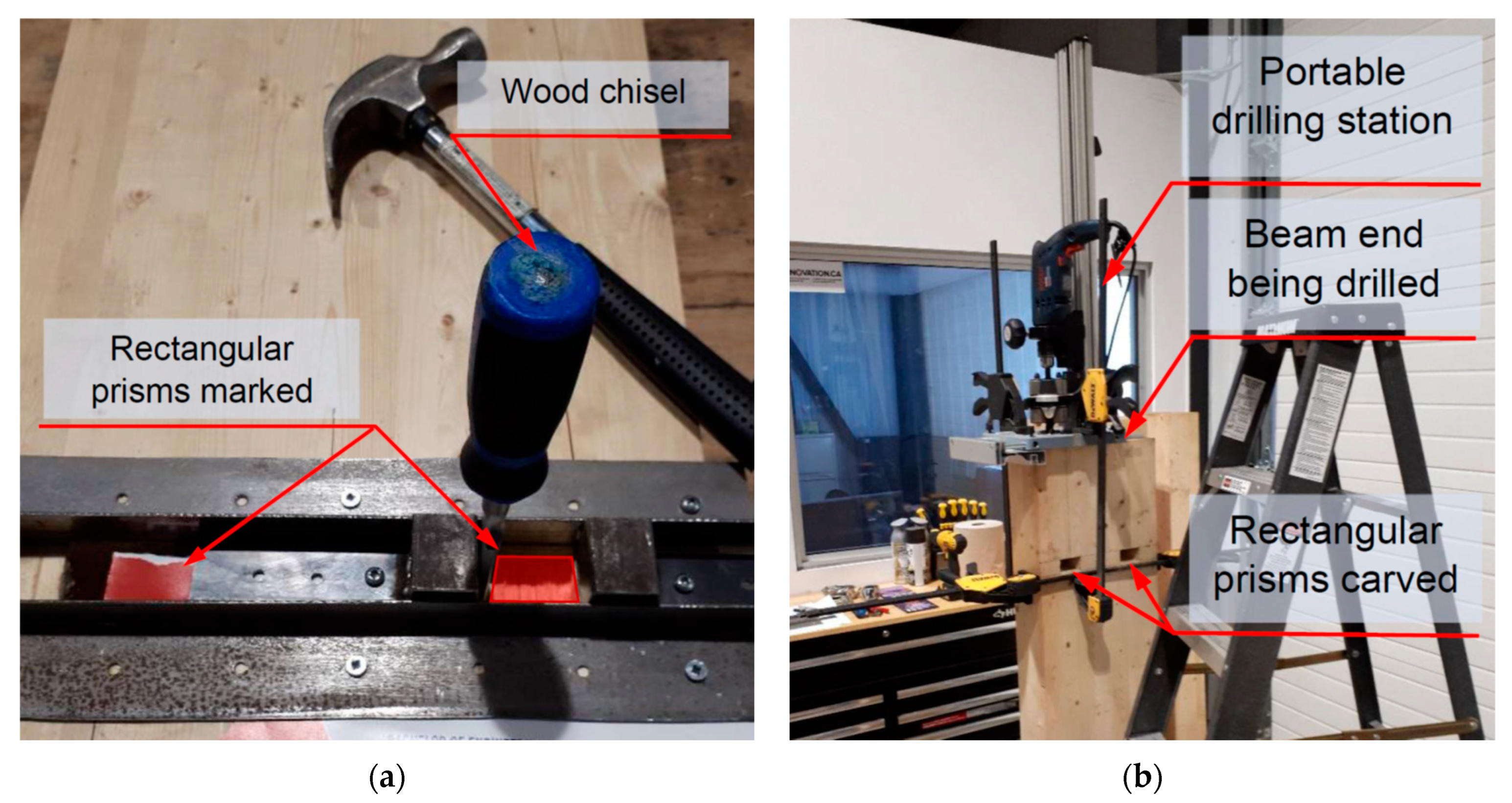
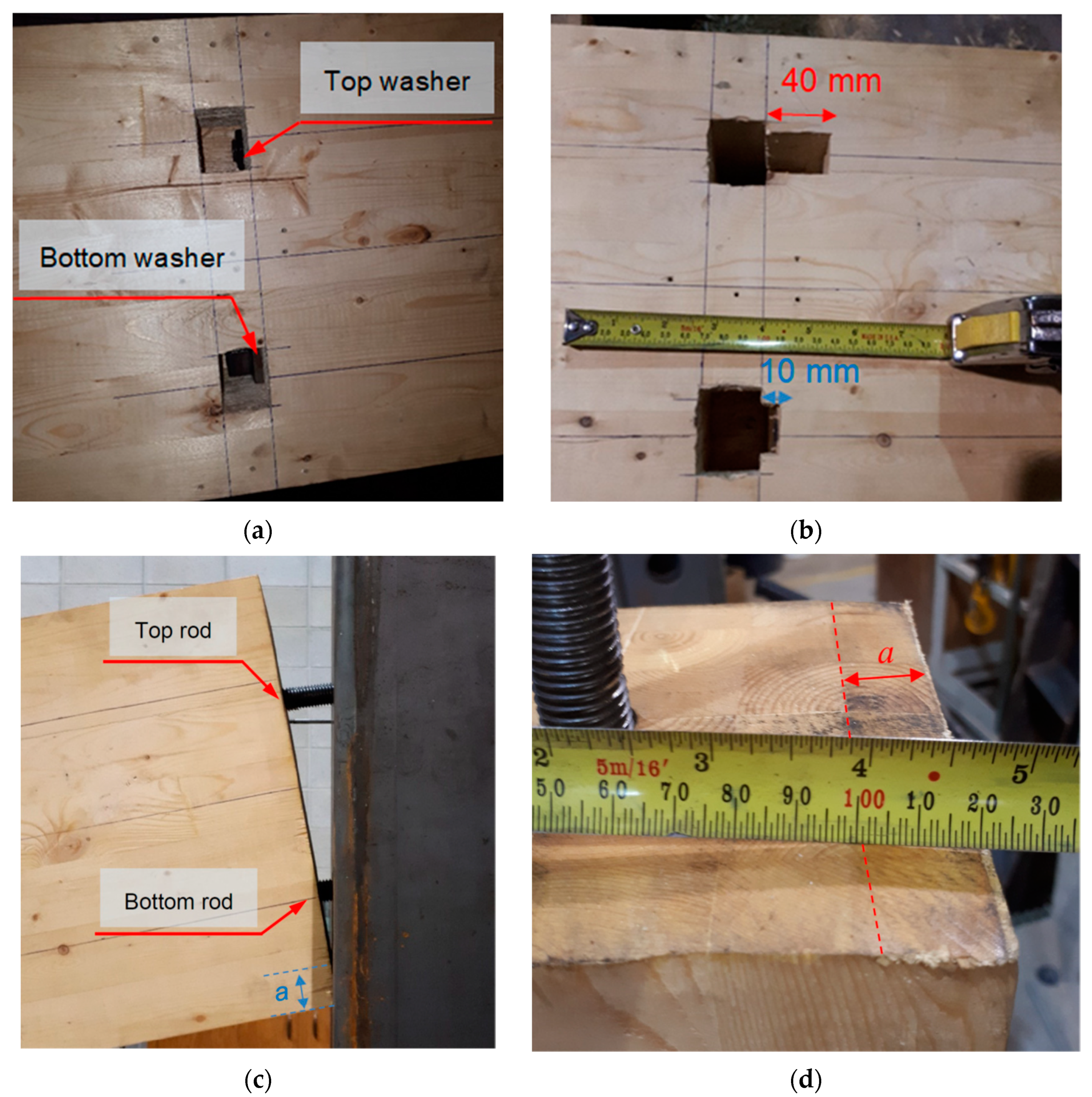
The threaded rods employed in the connections had 200 or 250-mm anchorage length. Two 30 mm thick rectangles, either 41.3 mm high for the 38.1 mm wide square washer or 54.0 mm high for the 50.8 mm wide square washer, were carved out using a wood chisel to accommodate the washer and nut at a depth of approximately 87 mm for the 38.1 mm wide square washer, or 93 mm for the 50.8 mm wide square washer, as shown in Figure 1a and Figure 1b, respectively. A 20.6 mm diameter hole was then drilled into the beam end in line and centred with each carved rectangular cavity on the beam wide face and horizontally centred along the beam narrow face to the required rod anchorage length (i.e., 200 or 250 mm) using a precise portable drilling station, as shown in Figure 2b.
2.3. Test Assembly Design
Before testing the full beam-end connection assembly, 37 pilot experiments were conducted prior to the current study to determine the pull-out strength of individual steel rods of varying anchorage lengths that were mechanically fastened with varying-sized square washers into glulam sections [19]. From the individual rod pull-out strength tests, the four configurations that yielded the most predictable results were selected for the full beam-end connection configurations presented in this paper. With the beam-end connection exhibiting bending moment, the top rod was subjected to tension; a lower portion of the wood section was subjected to compression; and the bottom rod was subjected to minimal tension since it is in the proximity of the neutral axis yet in the tension side of the connection. Using the results from the rod pull-out preceding tests reported by Hubbard and Salem [19] as the top rod tensile forces, the moment-resisting capacities of the connection with different rod anchorage lengths and washer sizes were determined. The bottom rod was not included for ease of calculation as it would add negligible tensile force when determining the connection moment-resisting capacity.
The compressive force at the bottom side of the connection is calculated based on the factored compressive resistance of glulam parallel to the grain as per Clause 7.5.8.4 of CAN/CSA O86-19 [22]. Several design modification factors are applied to the compressive resistance formula to accurately determine the actual compressive strength. Still, most of them can be omitted or equal to 1.0 due to the nature of the connection and the actual test conditions. For example, the section size factor (KZcg) can be omitted because the amount of wood being compressed in the connection is very small, and this factor is only considered when dealing with large volume of wood. The slenderness factor (KC) can be omitted since only a small section of the area is under compression and is fully supported within the connection. The load duration factor (KD) equals 1.15 as per Clause 12.2.1.6 of CAN/CSA O86-19 [22] since the glulam beam sections were tested under quick loading until failure (less than seven days loading duration). The system factor (KH) equals 1.0 since only an isolated connection is being tested (the connection is not part of a structural system). The service condition factor (KSc) and the treatment factor (KT) both equal 1.0 as per Clause 12.2.1.5 and Clause 12.2.1.7, respectively, of CAN/CSA O86-19 [22] since the beam sections were under dry service condition and were untreated.
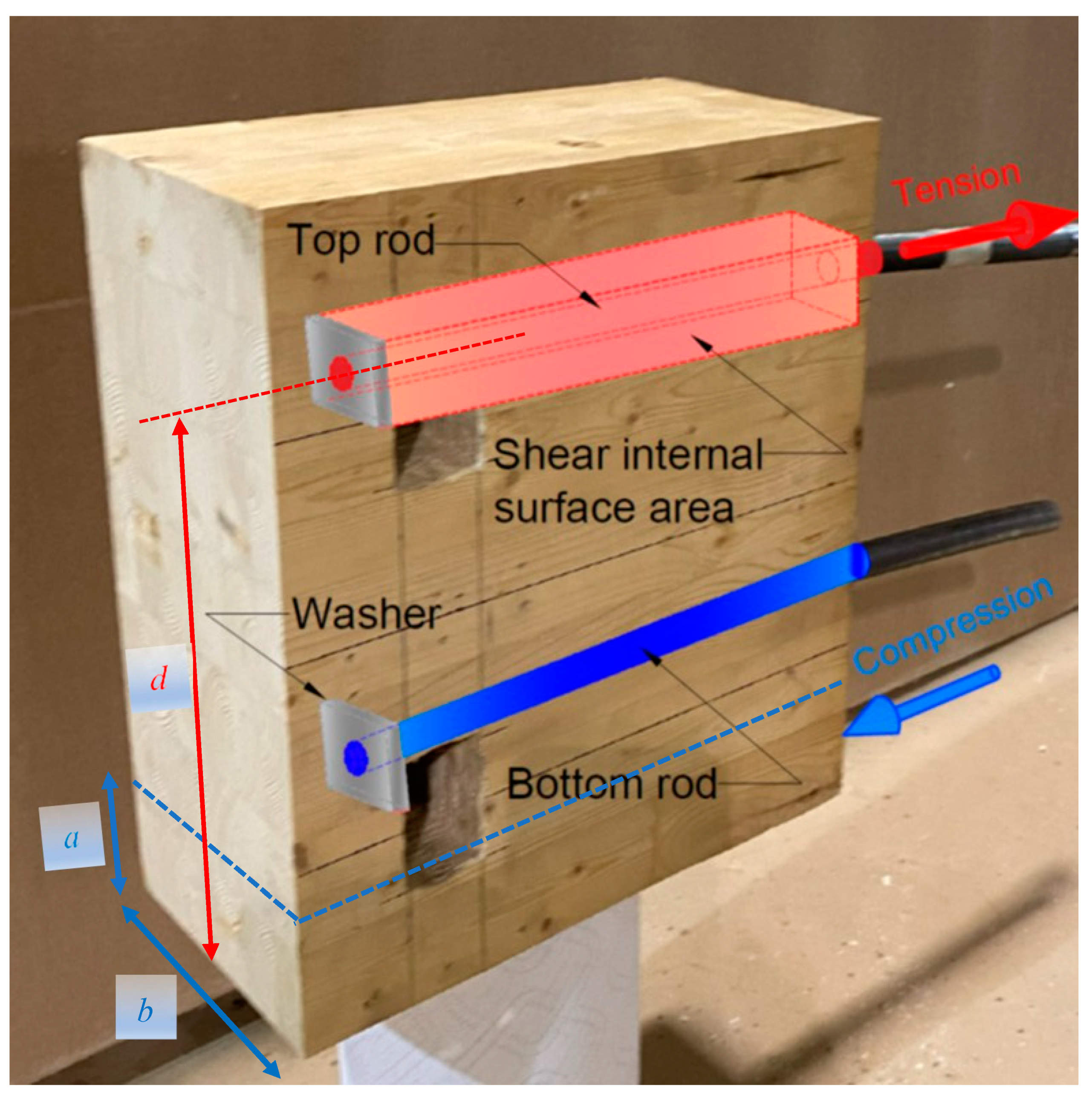
The specified parallel-to-the-grain compressive strength for the glulam beam sections (fc) equals 33.0 MPa, according to the Canadian Construction Materials Centre (CCMC) Evaluation report 13216-R [20]. The area being compressed (a × b) is the compression block at the bottom of the connection, where (a) is the compression block height, and (b) is the block width, which is 135 mm, as shown in Figure 3. The final value to account for is the resistance reduction factor (ϕ), which equals 0.8 as per Clause 7.5.8.4.2 of CAN/CSA O86-19 [22]. Combining all the above-mentioned values allowed the determination of the compressive force (C) that the compression block can resist, as shown in Equation (1).
C = ϕ fc (KD KH KSc KT) a × b
With the modification factor values inserted into Equation (1), the formula can be simplified to C = ϕ Fc a × b, where Fc equals the factored compressive resistance parallel to the wood grain, which equals 37.95 MPa. Assuming the beam section is in equilibrium at the connection (the tensile force equals the compressive force), thus the compression block height (a) can be determined, and the neutral axis of the connection can be located. Finally, the connection moment resistance (Mr) can be calculated using Equation (2) with the assistance of Figure 3.
where (T) is the tension force in the top rod (N); (d) is the distance from the midpoint of tension force to the bottom of the beam; and (a) is the height of the compression block (mm), as shown in Figure 3.
Mr = T (d − 0.5a)
According to the results of the tension tests of the preceding study conducted by Hubbard and Salem [19], the minimum estimated strengths at failure, along with the predicted moment resistances of the four connection configurations tested in the current study, are shown in Table 2. The failure of the tension tests with the 38.1 mm washers was the crushing of wood under the washer, which was the same as the predicted failure mode for the top rod of the two test configurations with the 38.1 mm washer. The two test configurations with the 50.8 mm washers had their minimum expected tensile forces greater than 90 kN, which is the average yielding force of the steel rods. Therefore, the strength of the steel rather than the wood’s strength was used to predict the connection moment resistance. Accordingly, the steel rod yielding and its ultimate tensile force were 90 and 104 kN, respectively.
2.4. Test Setup and Procedure
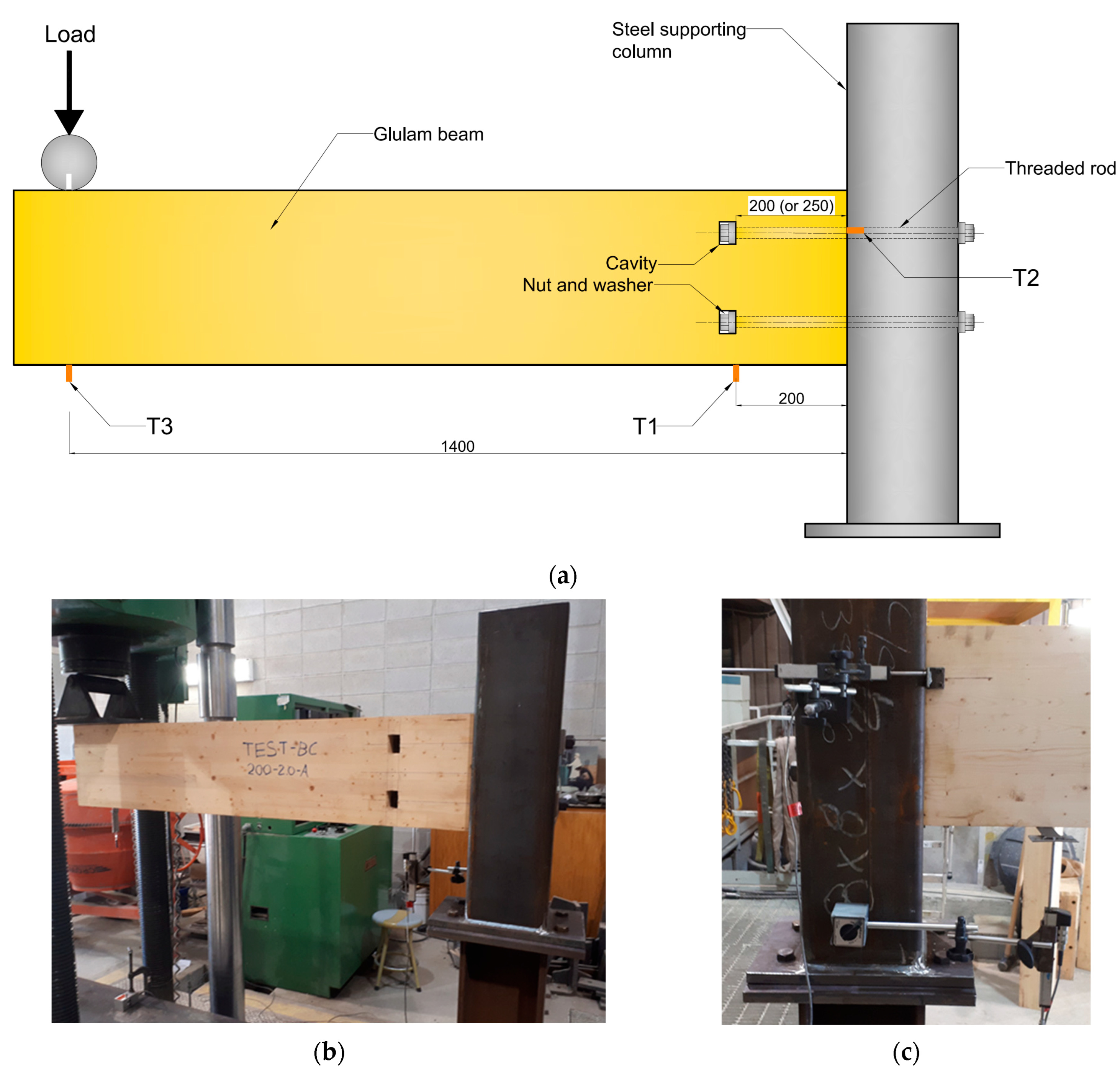
The cantilever beam was placed with a crane to connect the beam end to the steel supporting column within a Universal Testing Machine (UTM). The top and bottom steel rods were secured to a sturdy steel supporting column designed to sustain a substantially greater load than the maximum load anticipated to be applied on the strongest connection configuration. Then, the end of each rod was fastened to the glulam section using a steel nut and square washer, which were desirable for the connection configuration being tested. The test beams were not restrained against lateral buckling due to their cross-sectional small depth-to-width (d/b) ratio, which was less than 2.5 as per the CSA O86-19 [22] design standard. A rigid steel bar was attached to the underside of the beam and placed 200 mm from the column face to allow the installment of a linear variable differential transducer (LVDT), labelled T1, which was then used to measure the beam vertical displacements that were later used to calculate the rotations of the beam end against the sturdy vertical supporting steel column. A second steel bar was placed inline and perpendicular to the top rod, with another LVDT, labelled T2, installed against that bar to measure the gap between the beam end and the supporting column where the top rod is. A third steel bar was attached to the underside of the beam but at a 1400 mm from the column face with a draw-wire displacement transducer, labelled T3, attached to it to measure the beam’s vertical displacements in line with where the load is applied. A pinned steel support attachment was placed between the UTM crosshead and the beam’s top side at 1400 mm from the column face so that the load would always be applied vertically at the same location as the beam’s free end deflects during testing. Once the displacement transducers were in place and checked, the test assembly was loaded at 8.0 kN per minute. The slow loading rate was chosen to avoid unnecessary premature wood splits that might be caused by loading the test specimen too fast. Also, the loading rate of force per time versus displacement per time was chosen due to the same preventative measure of not loading too quickly. The test was terminated when the glulam beam-end connection experienced failure with no additional load gain. The full test setup of a general beam-end connection assembly is shown in Figure 4.
3. Experimental Results
The results presented in this paper are mainly the displacements measured by the LVDT located 200 mm from the column face, labelled T1. These displacements were then used to calculate the beam-end connection rotations and the associated loads applied, and the moment magnitudes applied on the beam-end connection were also calculated.
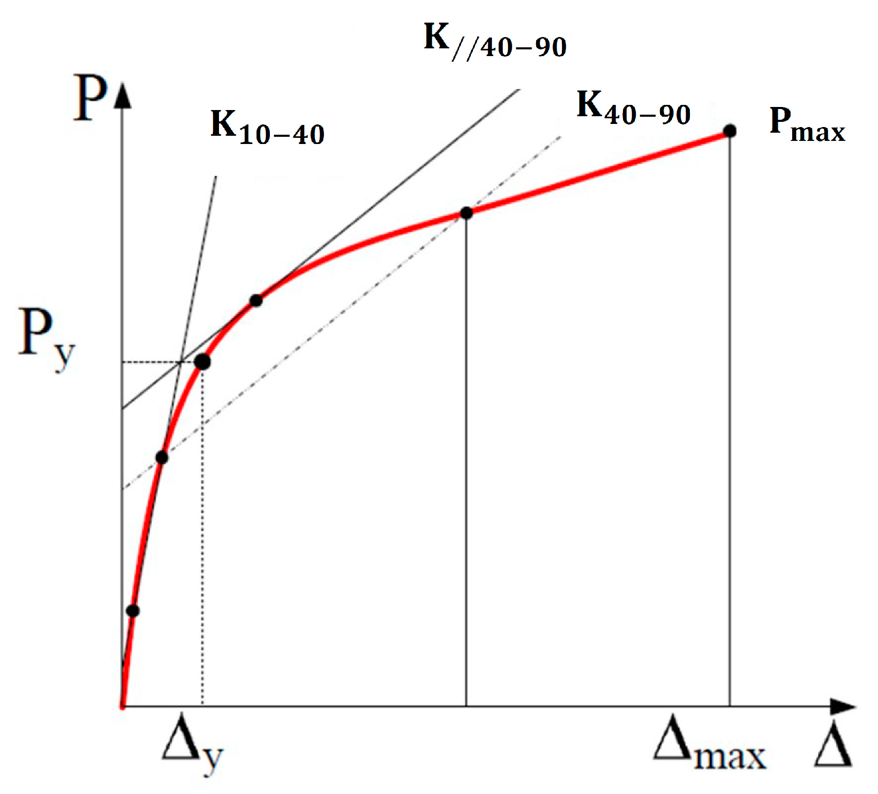
The initial stiffnesses, yielding, and maximum moments were determined using the method developed by Yasumura and Kawai [23], as it was found to provide the most consistent results for different types of timber beam connections compared to other published methods [24]. Applying this method, the beam connection’s initial stiffness (K10–40) was first calculated between 10% and 40% of the maximum applied load. Then, the yielding moment of the connection was estimated based on determining the intersection of the initial stiffness line (K10–40) and a straight-line drawn tangent to the moment-rotation curve, which is offset and parallel to the secant line plotted between 40% and 90% of the peak load. This point of intersection was then projected horizontally onto the moment-rotation curve to determine the yielding rotation of the connection. Finding the point of intersection is demonstrated in Figure 5.
The peak moment and its respective rotation of the connection were based on the maximum load reached by the connection just before any considerable load drop (greater than 5% drop in the applied load) occurred in conjunction with any observable failure in the wood within the connection. The connection rotation value at failure was based on the maximum rotation sustained before fracture failure in the steel rod or brittle failure in the wood. Accordingly, the connection ductility ratio was determined using the rotation value measured at the yielding moment and the rotation value measured at failure, as opposed to the deformation ratio, which uses the rotation values measured at the connection’s yielding and maximum moments. The reason for using the ductility ratio instead of the deformation ratio to represent the behaviour of the glulam beam-end connections tested in this study is that the connections did not exert brittle failure in the wood section once its maximum moment was reached. Instead, some of the connections had their top steel rod fail by yielding, and others had the wood under the washer compressed into the beam section for a significant displacement before any brittle failure occurred.
3.1. Failure Modes
The primary failure mode for the tests with the 38.1 mm washer was wood crushing under the washer of the top steel rod, as shown in Figure 6a, which confirms the predictions from the individual rod pull-out tests performed in a preceding study to this current one [19]. In this type of failure, the top washer compressed into the wood section by an average of 40 mm, whereas the bottom washer compressed into the wood section by an average of only 10 mm, as shown in Figure 6b. No shear rod pull-out or wood splitting was observed in the connection, as shown in Figure 6c. The compression block height (a) was observed and measured between 17 and 21 mm for all tests with the 38.1 mm washer, as shown in Figure 6d.
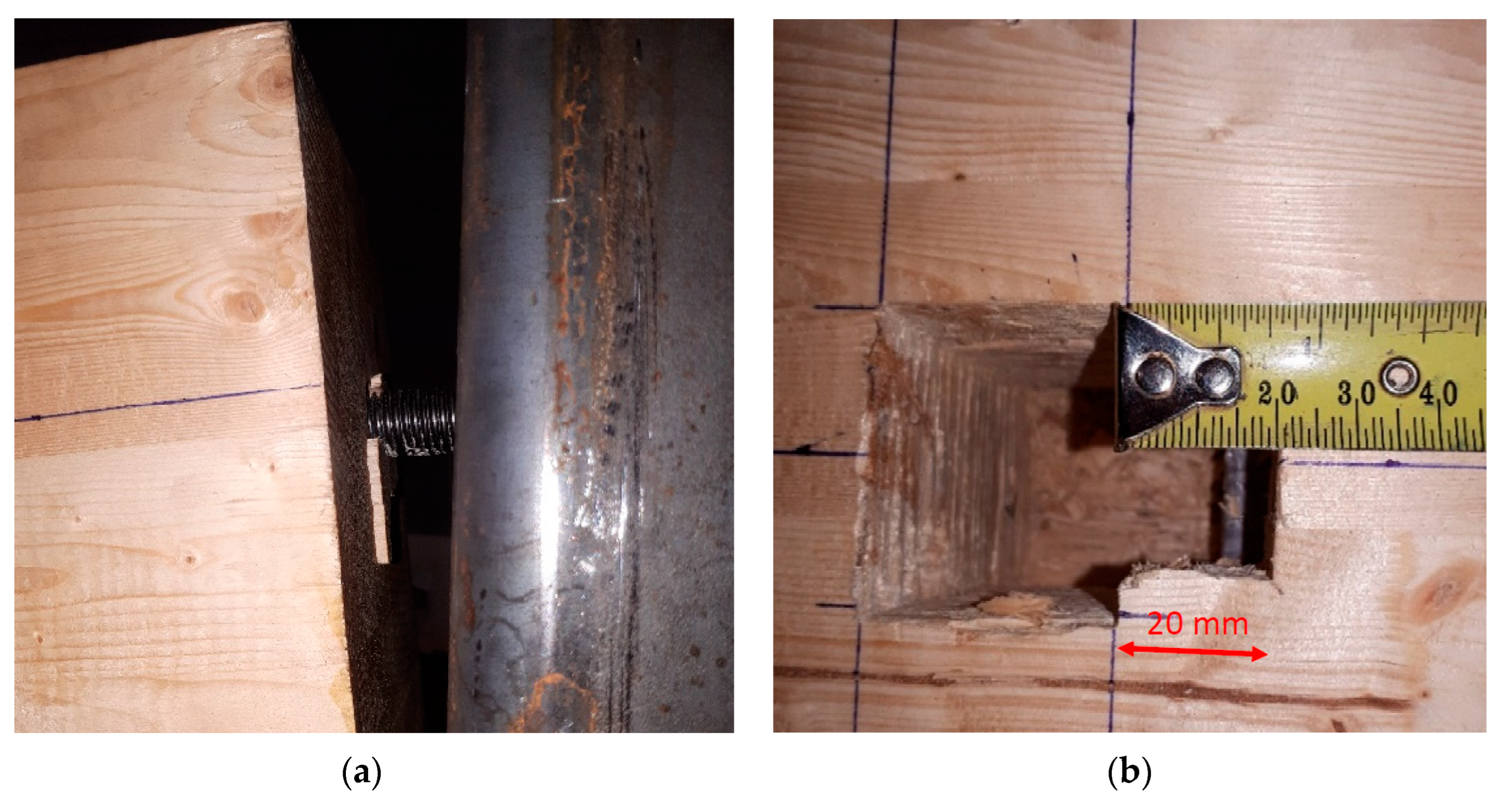
Test 200-1.5-A connection failed like other connections with 38.1 mm washers, except at the end when the top rod failed by shear rod pull-out, as shown in Figure 7a. The rod pull-out failure is because the 200 mm rod embedment length provided less wood surrounding it to resist shear stresses along the edges of the washers compared to connections with a 250 mm rod embedment length. As a result, the Test 200-1.5 connection configuration had more chance for the wood to shear along the washer’s four edges and throughout the embedment length once compressed into the wood section, decreasing the embedment length of the amount of wood resisting shear stresses. As shown in Figure 7b, the wood under the washer only compressed 20 mm compared to the 40 mm that the other tests with the 38.1 mm washers experienced.
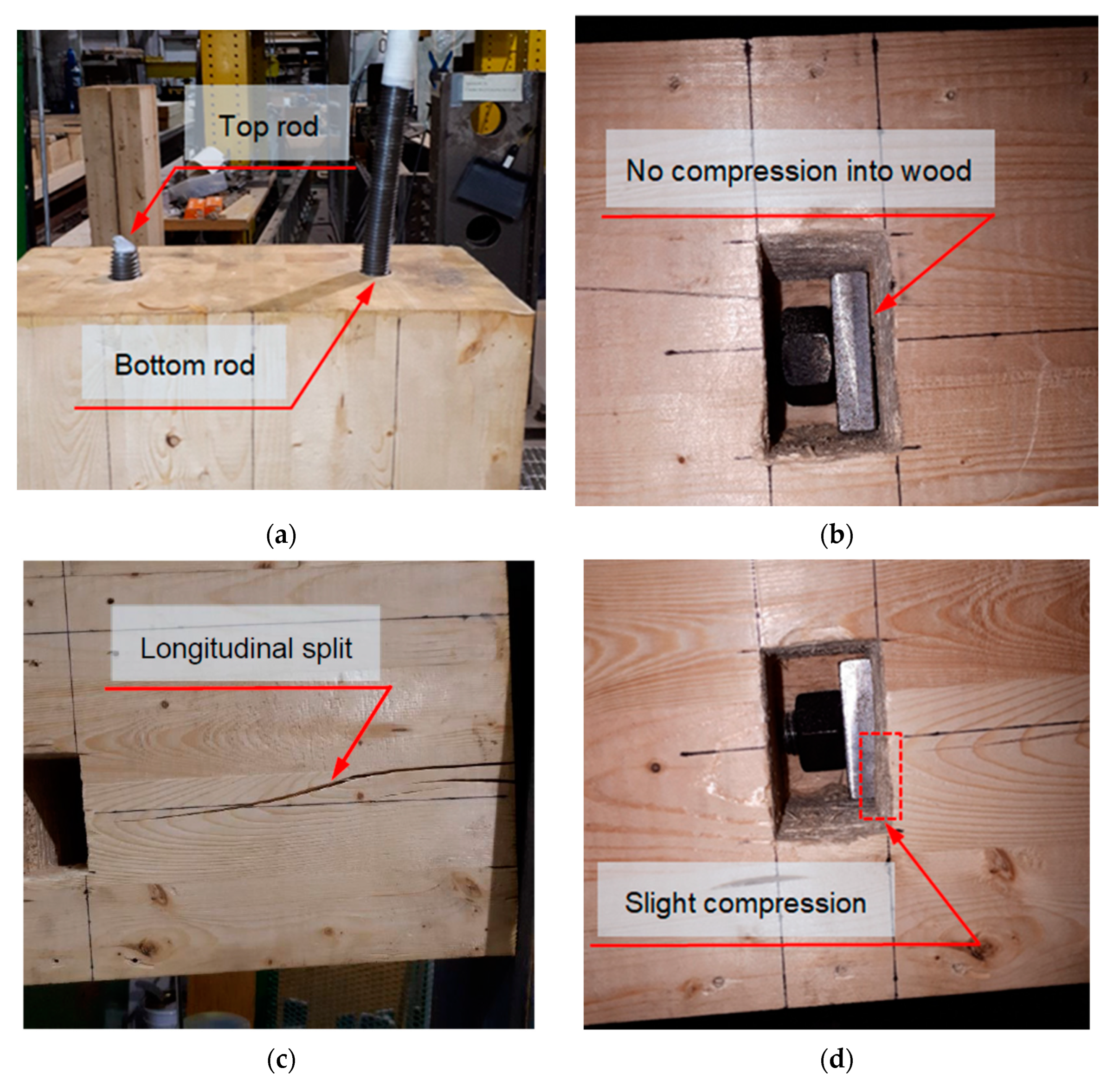
The primary failure for the connections with the 50.8 mm washers was the yielding of the top steel rod, as shown in Figure 8a, which confirms the prediction from the previous tension tests performed before this study [19]. A split was observed to form along the face of the beam on each side in line with the bottom rod, just above the compression zone, as shown in Figure 8b. Figure 8c shows the top washer having no noticeable deformation or compression into the wood section. Figure 8d shows the bottom washer having no noticeable deformation, but the washer slightly compressed into the wood section along its bottom edge.
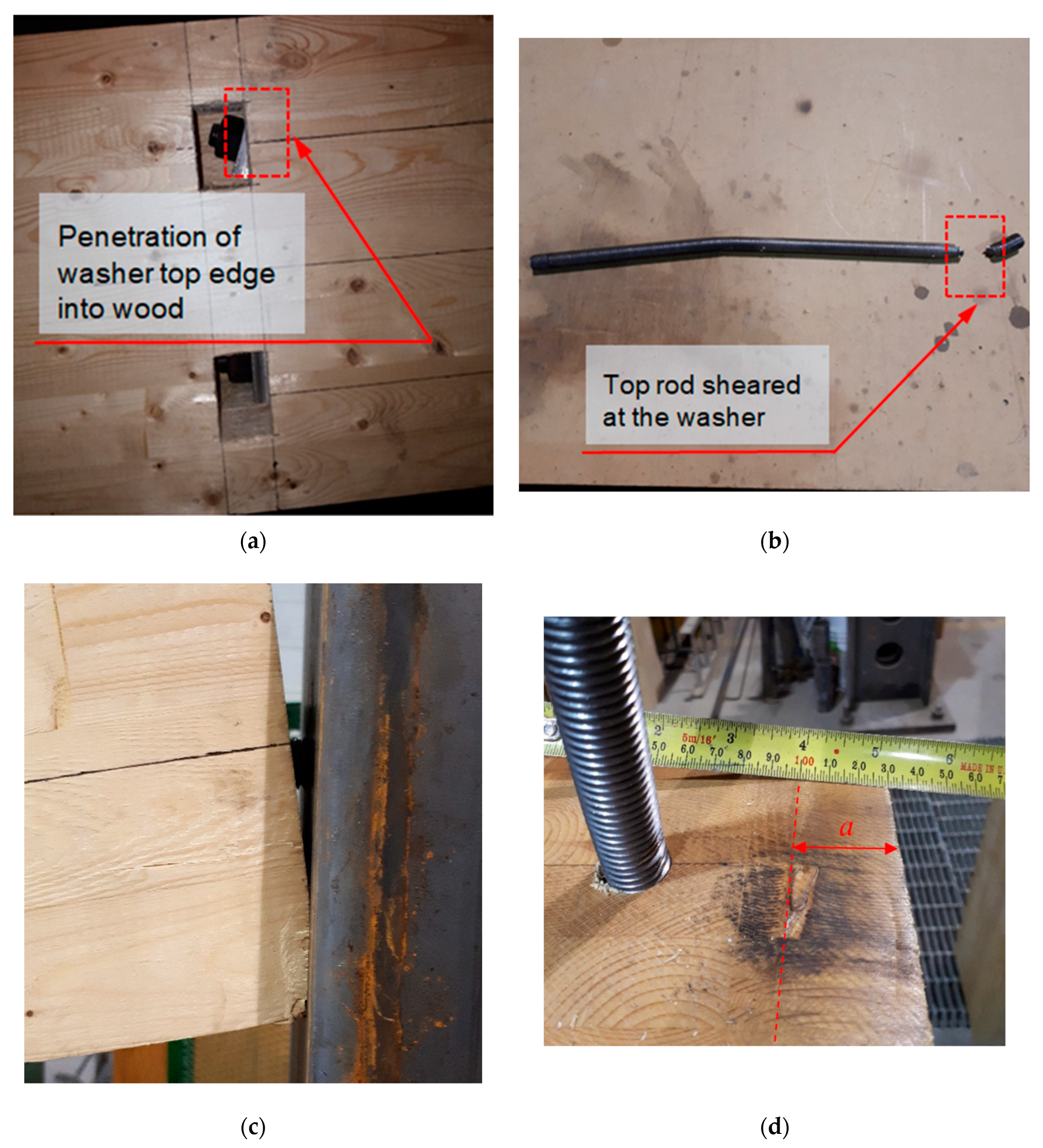
Test 250-2.0-B connection failed like other connections with the 50.8 mm washers, except at the end when the top rod had its washer compressed into the wood section before the rod sheared, as shown in Figure 9a. Figure 9b shows that the top steel rod failed at the intersection where the washer was bearing against the wood. Since the steel rod failed at the washer-wood interface, it could have caused slightly more rotation, making the washer apply more pressure along one edge instead of even pressure on the entire surface underneath the washer. The uneven pressure would cause the washer to start compressing into the wood section, allowing the beam to endure greater rotation values than similar connections with the 50.8 mm washers. As shown in Figure 9c, the beam experienced no splits along its face just above the compression zone. Also, since the beam could rotate more due to the washer compressing the wood on one edge, the compressive force contributed more towards the steel rod failure, preventing the wood in the compression zone from splitting. The compression block height (a) was observed and measured between 25 and 30 mm in all connections with the 50.8 mm washers, as shown in Figure 9d.
3.2. Moment-Rotation Relationships
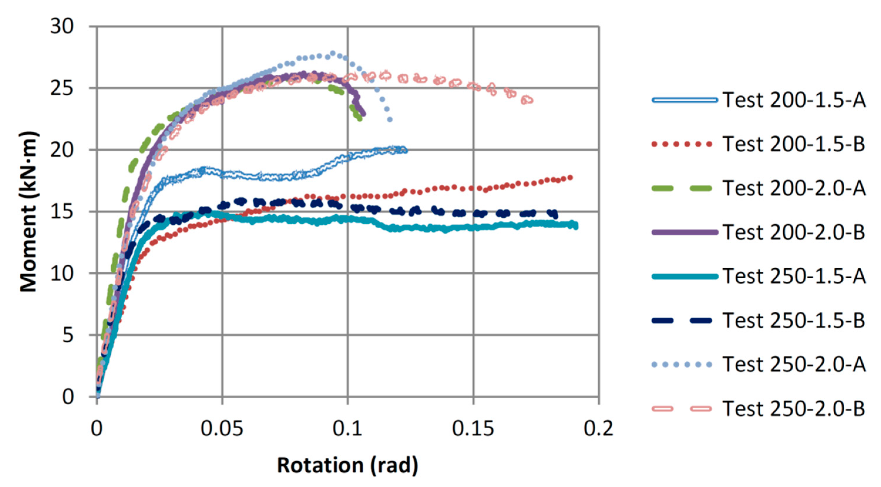
The moment-rotation relationships shown in Figure 10 illustrate that most connections had considerable ductility. The four tested connections with the 50.8 mm washers failed due to steel rod yielding, and most of those connections failed at rotation values greater than 0.1 radians. Whereas the four other connections with the small washers (38.1 mm) failed due to wood crushing under the washer, and all behaved in a more ductile manner than those with the large washers (50.8 mm), with most connections failing at rotation values greater than 0.175 radians. The general trend shows that the connections with the large washers (50.8 mm) had greater stiffness and moment resistance values than those with the small washers (38.1 mm); however, the connections with the small washers had higher ductility ratios. All connections had their yielding moments at a rotation of about 0.02 radians.
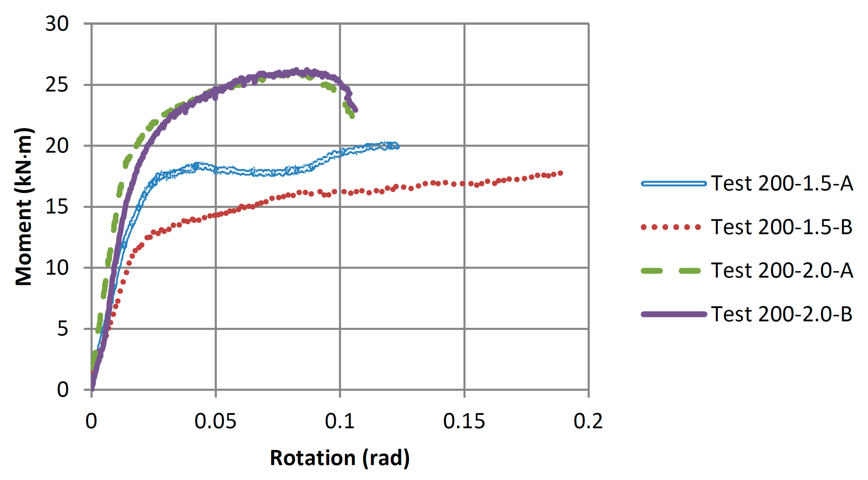
Figure 11 shows the effect of increasing the washer size from 38.1 mm to 50.8 mm on the moment-rotation relationships for the connections that utilized steel rods of 200 mm embedment length. It was noticed that the increase in the washer size increased the connection yielding moment capacity by about 35% (from an average of 12.77 to 17.28 kN·m) and the connection maximum moment by about 38% (from an average of 18.98 to 26.16 kN·m). The connection failure mode also changed with the increased washer size from wood crushing under the washer to steel rod yielding. The average ductility ratio of the connections with the 50.8 mm washers, which failed due to steel rod yielding, was 7.40. In comparison, those with the small washers (38.1 mm) failed due to wood crushing and had an average ductility ratio of 8.49. The failure of Test 200-2.0 connections was steel rod yielding, which is very predictable and explains why their moment-rotation curves are very similar. The failure of Test 200-1.5 connections was wood crushing under the washer, except for Test 200-1.5-A connection, which experienced a shear rod pull-out failure at the end of the test, as shown in Figure 7a. The shear rod pull-out failure explains why the Test 200-1.5-A connection had a greater moment resistance and a lesser ductility ratio when compared to Test 200-1.5-B connection.
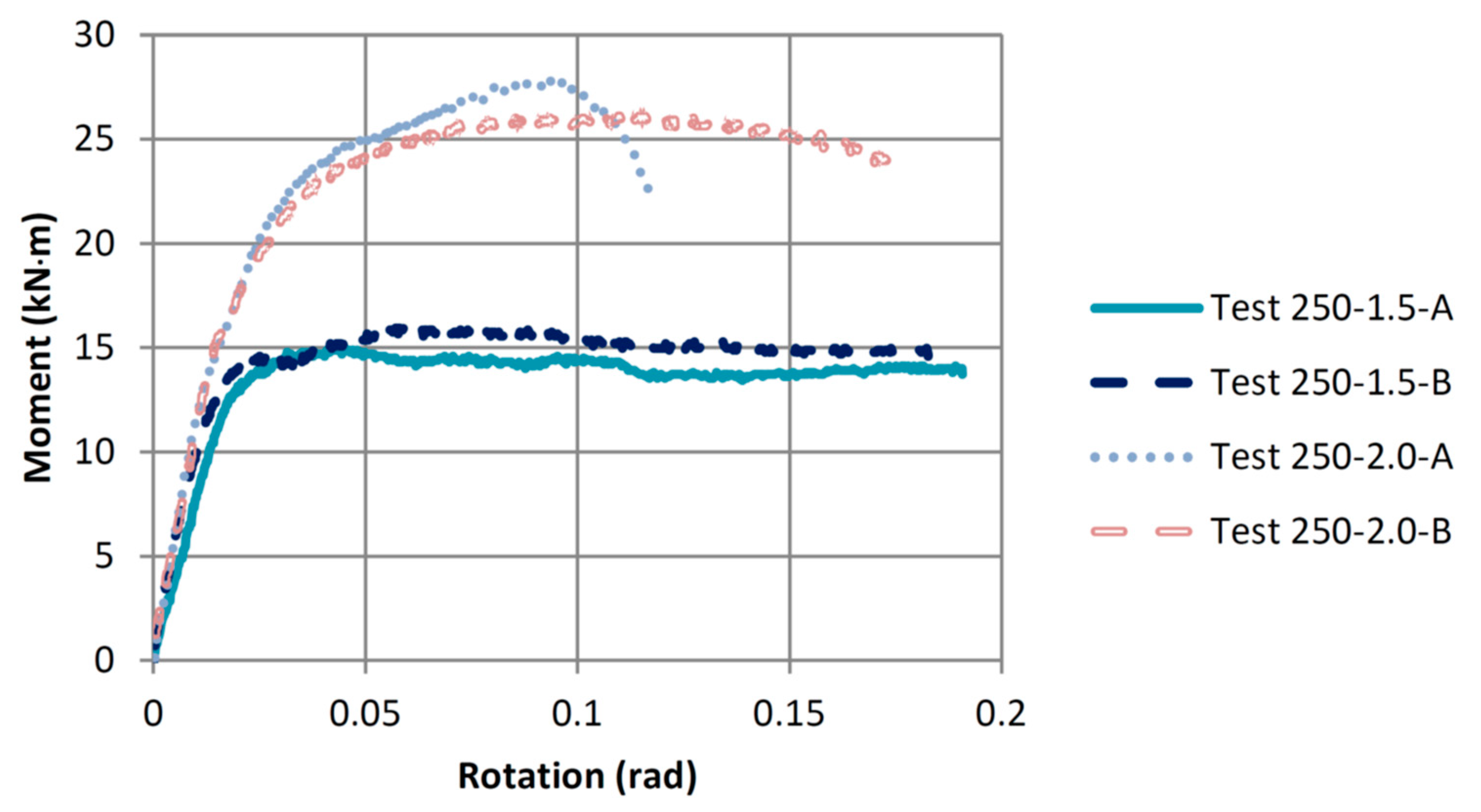
Figure 12 shows the effect of increasing the washer size from 38.1 mm to 50.8 mm on the moment-rotation relationships of the connections utilizing steel rods of 250 mm embedment length. It is noticed that the increase in the washer size increased the connection yielding moment capacity by about 58% (from an average of 10.51 to 16.60 kN·m) and the connection maximum moment by about 74% (from an average of 15.56 to 27.03 kN·m). Like the connections with the 200 mm rod embedment length, the failure mode of the connections with longer rod embedment length changed with the increase in the washer size from wood crushing under the washer to steel rod yielding. The average ductility ratio of the connections with the 50.8 mm washers, which failed due to steel rod yielding, was 8.25. In comparison, the connections with the small washers (38.1 mm) failed due to wood crushing and had an average ductility ratio of 15.17. The failure of both Test 250-1.5 connections (A and B) was wood crushing under the washer, which is why their moment-rotation curves are very similar. The failure of the Test 250-2.0-A connection was steel rod yielding, whereas the Test 250-2.0-B connection experienced wood crushing under the washer at the end of the test, as shown in Figure 9a. The wood crushing under the washer combined with the rod yielding failure explains why Test 250-2.0-B connection had a similar ductility ratio to those of Test 250-1.5 connections and a higher ductility ratio when compared to Test 250-2.0-A connection.
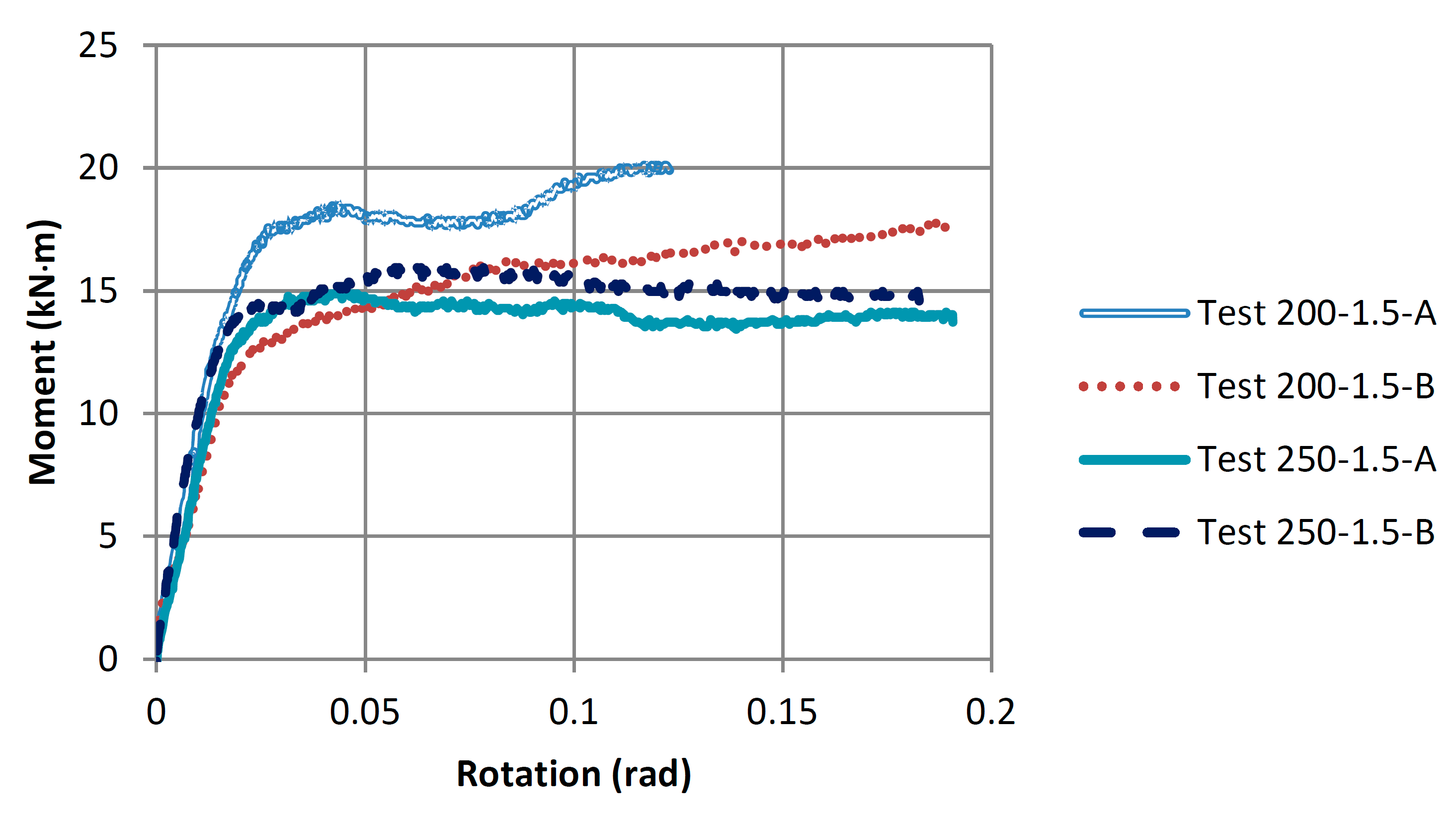
Figure 13 shows the effect of increasing the steel rod embedment length from 200 to 250 mm for the connections that utilized the small washers (38.1 mm). It is noticed that increasing the rod embedment length decreased the connection yielding moment capacity by about 18% (from an average of 12.77 to 10.51 kN·m). The increase in the rod embedment length also decreased the connection maximum moment by about 18% (from an average of 18.98 to 15.56 kN·m). However, the failure mode stayed the same for the connections with both embedment lengths, as wood crushing under the washer. The average ductility ratio of the connections with the 200 mm rod embedment length was 8.49, while 15.17 for the connections with a longer embedment length of 250 mm. The ductility ratios for both connection configurations would have been relatively the same, except that Test 200-1.5-A connection failed at the end of the test due to shear rod pull-out, which increased the connection strength but significantly decreased its ductility ratio.
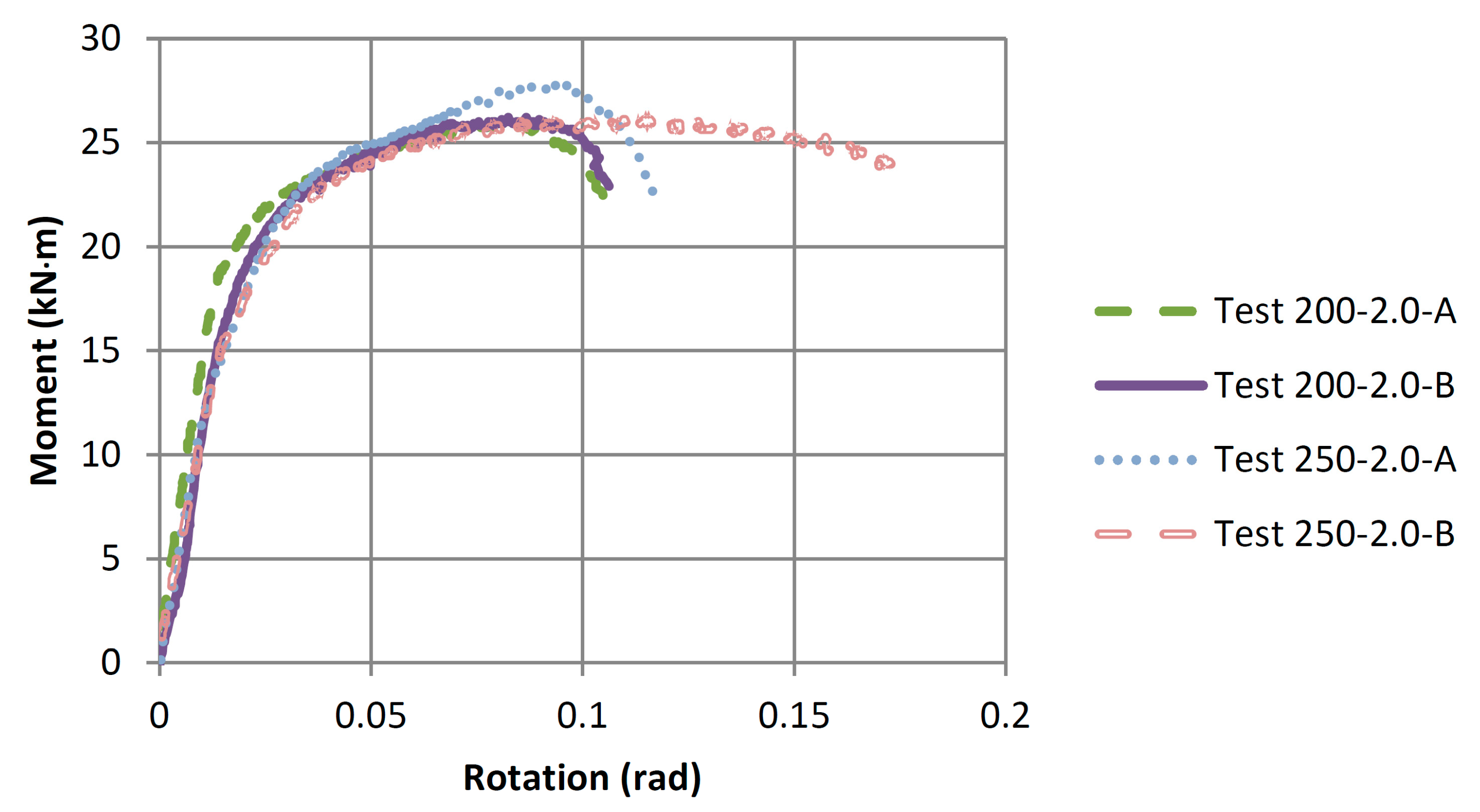
Figure 14 shows the effect of increasing the steel rod embedment length from 200 to 250 mm for the connections that utilized the larger washers (50.8 mm). It was noticed that increasing the rod embedment length had very little effect on the connection yielding moment capacity (from an average of 17.28 to 16.60 kN·m) and the connection maximum moment capacity (from an average of 26.16 to 27.03 kN·m). Like the connections with the small washer, the failure mode stayed the same for the connections with both embedment lengths, as yielding of the steel rod. The average ductility ratio of the connections with the 200 mm rod embedment length was 7.40, while for the connections with the 250 mm embedment length, the ductility ratio was 8.25. Since the failure of the connections with both embedment lengths and the same larger washer size (50.8 mm) yielded steel rods, there was expected to be very little difference in the results, as steel material behaviour is more predictable and consistent when it fails. Accordingly, if the steel rod is the only component failing in those connections, the connection bending strength can be predicted with a high degree of certainty.
3.3. Summary of Results and Discussion
Table 3 summarizes all results, including the calculated moment resistance, yielding moment, maximum moment, and ductility ratio for the four connection configurations experimentally examined in this study.
Test 200-1.5 connections averaged a maximum moment of 19.0 kN·m, approximately 16% greater than its predicted value, calculated at 16.4 kN·m. Test 250-1.5 connections with the same small washers but longer rod embedment length (250 mm) averaged a maximum moment of 15.6 kN·m, 15% less than the connection moment resistance calculated at 18.4 kN·m. The reason why Test 200-1.5 connections had a greater increase in the actual maximum moment versus its calculated maximum moment as compared to Test 250-1.5 connections could be attributed to two things, (a) the bottom rod added small increments to the moment resistance of the connection due to its location being slightly above the wood compression block (above the connection neutral axis); and (b) the calculation of the moment resistance of the connection only considered the direct tensile force on the top steel rod without considering any added bending effect that could have eventually developed due to the beam rotating against the supporting sturdy steel column.
One advantage of utilizing longer rod embedment length when comparing the behaviour of the small-washer connection configurations is the increase in the connection ductility ratio; however, this caused a decrease in the connection moment resistance [19]. For instance, the average ductility ratio for Test 200-1.5 connections was 8.5, while the average ductility ratio for Test 250-1.5 connections increased to 15.2 (about a 79% increase). However, the ductility ratios for similar connections with 200 mm and 250 mm rod embedment lengths utilized with the large washers were slightly below 8.5. This can be attributed to the steel rod yielding failure exhibited by the connections compared to the wood crushing failure exhibited by the connections with the small washers.
Regardless of the steel rod embedment length, the connection configurations that utilized large washers had their averaged maximum moment and yielding moment values almost the same. For example, the connections with the large washers had an average yielding moment value of 16.9 kN·m, about 17% lower than the connections’ predicted moment resistance value, calculated at 20.3 kN·m. Meanwhile, the connections’ averaged maximum moment value was 26.6 kN·m, about 14% greater than the predicted moment resistance value, calculated at 23.3 kN·m. An explanation for the connections’ lower average yielding moment value than its calculated value is that the top rod was not subjected to only tensile force but also bending moment. Thus, as shown in Figure 8a and Figure 9b, the top steel rod was bent at the interface between the beam end and the column side. Also, with the increased beam rotations, the top rod started to bend further and yielded earlier than it should have, like in the connections with the small washers (38.1 mm).
4. Conclusions and Recommendations
Due to the limited budget and time constraint of this research project and for the sake of investigating more variables, only two replicates were tested for each of the four connection configurations experimentally investigated in this study. Although it could be recommended to have more replicates tested to verify results, the correlation between the results obtained for the four different connection configurations allowed reasonable confidence in the outcomes of this new experimental study. Accordingly, the following conclusions have been drawn based on the experimental results and the analyses performed afterward.
- (1)
- The new connection design parameters (i.e., rod anchorage length and washer size) can promote either a steel rod-yielding failure, which is stronger and predictable, or a wood crushing failure, which is less predictable but can provide the connection with a high ductility ratio.
- (2)
- Increasing the rod embedment length slightly reduces the bending strength of the connection due to the uneven pressure under the washer; however, it significantly increases the connection ductility ratio when the failure mode is wood crushing under the washer.
- (3)
- The increase in the washer size caused the largest gain in the connection strength as it increased the wood area to be crushed and the internal shear surface area of wood along the washer perimeter, which also avoided the rod pull-out failure.
- (4)
- The increase in the square washer size from 38.1 mm to 50.8 mm did not show any ill effect due to the increased beam rotations, but from previous tension tests [19], a larger square washer (63.5 mm × 63.5 mm) was observed to cause splitting in the wood underneath and should therefore be avoided.
- (5)
- The formulas shown in Equations (1) and (2) are plausible for the glulam beam-end connection configurations experimentally examined in this study. However, more tests need to be performed to estimate the bending factor that caused the connection to fail at slightly smaller moment values than if the top rod was under pure tension instead of being subjected to combined tensile and bending forces.
From a practical point of view, considering a supported glulam beam spanning an average length of 4.0 to 6.0 m (a common span in framed timber buildings) and has a cross-section size the same as the one utilized in this study, the maximum moment resistance of such beam section is calculated at about 70.5 kN·m as per CSA O86-19 [22]. Meanwhile, knowing that the strongest connection configuration experimentally examined in this study (Test 200-2.0 connections) had an average yielding moment of approximately 17.0 kN·m, the bending moment utilization factor of the strongest connection configuration presented in this paper, if used with such beam, is about 24%. However, in a real-life scenario, a structural element such as a glulam beam is usually loaded to approximately 50% to 70% of its design capacity, considering a reasonable margin of safety. Accordingly, this suggests a maximum possible moment utilization factor that ranges between 34% and 48% for such beam-end connection, which is quite large for a timber connection and confirms a considerable moment-resisting capability of the timber connection configurations proposed in this new study.
Author Contributions
Conceptualization, C.H. and O.S.; Methodology, C.H. and O.S.; Formal analysis, C.H.; Investigation, C.H. and O.S.; Resources, O.S.; Data curation, C.H.; Writing—original draft, C.H.; Writing—review & editing, O.S.; Visualization, C.H.; Supervision, O.S.; Project administration, O.S.; Funding acquisition, O.S. All authors have read and agreed to the published version of the manuscript.
Funding
This research project was funded using a Discovery Grant awarded to the second author by the Natural Sciences and Engineering Research Council of Canada (NSERC).
Data Availability Statement
The original contributions presented in the study are included in the article, further inquiries can be directed to the corresponding author.
Acknowledgments
The authors thank lab technologists Conrad Hagstrom and Rob Timoon for their great assistance in the Civil Engineering Structures Laboratory at Lakehead University.
Conflicts of Interest
The authors declare no conflict of interest.
References
- NRCC. National Building Code of Canada 2020; National Research Council of Canada: Ottawa, ON, Canada, 2021. [Google Scholar]
- Murty, B.; Asiz, A.; Smith, I. Wood and engineered wood product connections using small steel tube fasteners: An experimental study. J. Inst. Wood Sci. 2008, 18, 59–67. [Google Scholar] [CrossRef]
- Andreolli, M.; Piazza, M.; Tomasi, R.; Zandonini, R. Ductile moment-resistant steel-timber connections. Proc. Inst. Civ. Eng. Struct. Build. 2011, 164, 65–78. [Google Scholar] [CrossRef]
- Humbert, J.; Lee, S.; Park, J.; Park, M. Moment resistance of post-and-beam joints with concealed metallic connectors. In Proceedings of the 13th World Conference on Timber Engineering, Quebec City, QC, Canada, 10–14 August 2014; Available online: https://static.sched.com/hosted_files/wcte2014/9a/ABS340_Lee_web.pdf (accessed on 12 January 2024).
- Gattesco, N.; Toffolo, I. Experimental study on multiple-bolt steel-to-timber tension joints. Mater. Struct. 2004, 37, 129–138. [Google Scholar] [CrossRef]
- Zarnani, P.; Quenneville, P. Design method for coupled-splice timber moment connections. In Proceedings of the 13th World Conference of Timber Engineering, Quebec City, QC, Canada, 10–14 August 2014. [Google Scholar] [CrossRef]
- Xu, B.H.; Bouchaïr, A.; Racher, P. Mechanical behavior and modeling of dowelled steel-to-timber moment-resisting connections. J. Struct. Eng. 2015, 141, 04014165. [Google Scholar] [CrossRef]
- Xiong, H.; Liu, Y. Experimental study of the lateral resistance of bolted Glulam Timber Post and Beam Structural systems. J. Struct. Eng. 2014, 142, E4014002. [Google Scholar] [CrossRef]
- Rebouças, A.S.; Mehdipour, Z.; Branco, J.M.; Lourenço, P.B. Ductile moment-resisting timber connections: A review. Buildings 2022, 12, 240. [Google Scholar] [CrossRef]
- Fang, L.; Wang, L.; Qu, W.; Zhang, S. Mechanical performance of glulam beam-column moment-resisting connections with self-tapping screws as fasteners. J. Build. Eng. 2022, 54, 104586. [Google Scholar] [CrossRef]
- Barillas, E.G. Capacity of Connections in Glulam with Single and Multiple Glued in Steel Rods. Master’s Thesis, University of British Columbia, Vancouver, BC, Canada, 2014. [Google Scholar] [CrossRef]
- Fragiacomo, M.; Batchelar, M. Timber frame moment joints with glued-in steel rods, I: Design. J. Struct. Eng. 2012, 138, 789–801. [Google Scholar] [CrossRef]
- Steiger, R.; Gehri, E.; Widmann, R. Pull-out strength of axially loaded steel rods bonded in glulam parallel to the grain. Mater. Struct. 2006, 40, 69–78. [Google Scholar] [CrossRef]
- Tomasi, R.; Zandonini, R.; Piazza, M.; Andreolli, M. Ductile end connections for glulam beams. Struct. Eng. Int. 2008, 18, 290–296. [Google Scholar] [CrossRef]
- Oh, J. Timber Moment Connections Using Glued-In Steel Rods. Master’s Thesis, University of British Columbia, Vancouver, BC, Canada, 2016. [Google Scholar] [CrossRef]
- Hunger, F.; Stepinac, M.; Rajcic, V.; Van de Kuilen, J.W.G. Pull-compression tests on glued-in metric thread rods parallel to grain in glulam and laminated veneer lumber of different timber species. Eur. J. Wood Wood Prod. 2016, 74, 379–391. [Google Scholar] [CrossRef]
- Fragiacomo, M.; Batchelar, M.L. Timber frame moment joints with glued-in steel rods. II: Experimental investigation of long-term performance. J. Struct. Eng. 2012, 138, 802–811. [Google Scholar] [CrossRef]
- Batchelar, M.L.; McIntosh, K.A. Structural joints in glulam. In Proceeding of the 5th World Conference on Timber Engineering, Montreux, Switzerland, 17–20 August 1998; Volume 1, pp. 289–296. Available online: https://www.timberdesign.org.nz/wp-content/uploads/2018/05/Structural-Joints-In-Glulam.pdf (accessed on 12 January 2024).
- Hubbard, C.; Salem, O. Experimental determination of the pull-out strength of mechanically fastened steel rods into glulam beam sections having different rod lengths and washer sizes. In Engineering Structures; Elsevier: Amsterdam, The Netherlands, 2021; Volume 240. [Google Scholar] [CrossRef]
- CCMC. Evaluation Report: Nordic Lam. In Canadian Construction Materials Centre Report No. CCMC 13216-R; National Research Council Canada: Ottawa, ON, Canada, 2018. [Google Scholar]
- G40.20-04/G40.21-13; General Requirements for Rolled or Welded Structural Quality Steel. Canadian Standards Association (CSA): Rexdale, ON, Canada, 2013.
- CSA O86-19; Engineering Design in Wood. Canadian Standards Association (CSA): Mississauga, ON, Canada, 2019.
- Yasumura, M.; Kawai, N. Estimating seismic performance of wood-framed structures. In Proceedings of the I.W.E.C., Montreux, Switzerland, 17–20 August 1998; Volume 2, pp. 564–571. [Google Scholar]
- Muñoz, W.; Salenikovich, A.; Mohammad, M.; Quenneville, P. Determination of Yield Point and Ductility of Timber Assemblies: In Search for a Harmonised Approach. Materials Science. 2008. Available online: http://support.sbcindustry.com/Archive/2008/june/Paper_149.pdf (accessed on 12 January 2024).
Figure 1.
Connection configurations: (a) with a 38.1 mm wide square washer; and (b) with a 50.8 mm wide square washer.
Figure 1.
Connection configurations: (a) with a 38.1 mm wide square washer; and (b) with a 50.8 mm wide square washer.

Figure 2.
Preparation of a beam connection: (a) a beam section being chiselled; (b) a beam section being drilled.
Figure 2.
Preparation of a beam connection: (a) a beam section being chiselled; (b) a beam section being drilled.

Figure 3.
A schematic of a general beam-end connection configuration.

Figure 4.
Full test setup of a general beam-end connection test assembly: (a) schematic of a general test setup; (b) front side of assembly setup; (c) back side of assembly setup.
Figure 4.
Full test setup of a general beam-end connection test assembly: (a) schematic of a general test setup; (b) front side of assembly setup; (c) back side of assembly setup.

Figure 5.
Yasumura and Kawai’s method for finding the yielding moment of a timber beam connection [23].
Figure 5.
Yasumura and Kawai’s method for finding the yielding moment of a timber beam connection [23].

Figure 6.
Test failures of beam connection with 38.1 mm (1.5 inches) washer: (a) top and bottom washers after failure; (b) depth of the top and bottom washer compressed into the wood section; (c) rotation of beam end; and (d) height of the compression block.
Figure 6.
Test failures of beam connection with 38.1 mm (1.5 inches) washer: (a) top and bottom washers after failure; (b) depth of the top and bottom washer compressed into the wood section; (c) rotation of beam end; and (d) height of the compression block.

Figure 7.
Test 200-1.5-A connection failure: (a) top rod shear pull-out failure; and (b) compressed depth of top washer into the wood section.
Figure 7.
Test 200-1.5-A connection failure: (a) top rod shear pull-out failure; and (b) compressed depth of top washer into the wood section.

Figure 8.
Test 200-2.0-A connection failure: (a) connection end with the top rod snapped; (b) split along the face of the beam just above the compression zone; (c) top washer with no deformation to wood; and (d) bottom washer with little deformation to wood.
Figure 8.
Test 200-2.0-A connection failure: (a) connection end with the top rod snapped; (b) split along the face of the beam just above the compression zone; (c) top washer with no deformation to wood; and (d) bottom washer with little deformation to wood.

Figure 9.
Test 250-2.0-B connection failure: (a) top and bottom washers after failure; (b) top rod sheared at the edge of the washer; (c) compression of wood with no splits in the compression zone; and (d) height of the compression block.
Figure 9.
Test 250-2.0-B connection failure: (a) top and bottom washers after failure; (b) top rod sheared at the edge of the washer; (c) compression of wood with no splits in the compression zone; and (d) height of the compression block.

Figure 10.
Moment-rotation relationships for all eight connection specimens.

Figure 11.
Comparison of the moment-rotation relationships of the connections utilizing the same shorter rod embedment length (200 mm) with two different washer sizes (38.1 mm and 50.8 mm).
Figure 11.
Comparison of the moment-rotation relationships of the connections utilizing the same shorter rod embedment length (200 mm) with two different washer sizes (38.1 mm and 50.8 mm).

Figure 12.
Comparison of the moment-rotation relationships of the connections utilizing the same longer embedment length (250 mm) with two different washer sizes (38.1 and 50.8 mm).
Figure 12.
Comparison of the moment-rotation relationships of the connections utilizing the same longer embedment length (250 mm) with two different washer sizes (38.1 and 50.8 mm).

Figure 13.
Comparison of the moment-rotation relationships of the connections utilizing the same smaller washer (38.1 mm) with two different rod embedment lengths (200 and 250 mm).
Figure 13.
Comparison of the moment-rotation relationships of the connections utilizing the same smaller washer (38.1 mm) with two different rod embedment lengths (200 and 250 mm).

Figure 14.
Comparison of the moment-rotation relationships of the connections utilizing the same larger washer (50.8 mm) with two different rod embedment lengths (200 and 250 mm).
Figure 14.
Comparison of the moment-rotation relationships of the connections utilizing the same larger washer (50.8 mm) with two different rod embedment lengths (200 and 250 mm).


Table 1.
The 5th percentile mechanical properties of glulam sections with 24F-ES/NPG stress grade [20].
Table 1.
The 5th percentile mechanical properties of glulam sections with 24F-ES/NPG stress grade [20].
| Property | Unit (MPa) |
|---|---|
| Bending moment, fb | 30.7 |
| Longitudinal shear, fv | 2.5 |
| Compression perpendicular to the grain, fcp | 7.5 |
| Compression parallel to the grain, fc | 33.0 |
| Tension parallel to the grain, ft | 20.4 |
| Tension perpendicular to the grain, ftp | 0.51 |
| Modulus of elasticity, E | 13,100 |
Table 2.
Concealed beam-end connection tests matrix.
| Test Configuration ID | Test Replicates | Embedment Length (mm) | Washer Size (mm) | Average Tensile Force (kN) | Maximum Moment Resistance (kN·m) |
|---|---|---|---|---|---|
| Test 200-1.5 | 2 | 200 | 38.1 | 71.9 | 16.4 |
| Test 200-2.0 | 2 | 200 | 50.8 | 103.2 (steel 104.0) | 23.3 (20.3 yielding) |
| Test 250-1.5 | 2 | 250 | 38.1 | 80.9 | 18.4 |
| Test 250-2.0 | 2 | 250 | 50.8 | 138.4 (steel 104.0) | 23.3 (20.3 yielding) |
Notes: For the test configuration ID, 200 and 250 are the rod embedment lengths in (mm); 1.5 and 2.0 are the square washer sizes in (inches).
Table 3.
Results summary for all beam-end connection configurations tested.
| Test Configuration ID | Initial Stiffness (kN·m/rad) | Myield (kN·m) | Yield Rotation (Rad) | Mmax (kN·m) | Failure Rotation (Rad) | Ductility Ratio | Estimated Mmax (kN·m) |
|---|---|---|---|---|---|---|---|
| 200-1.5-A | 831.47 | 13.59 | 0.0164 | 20.10 | 0.1229 | 7.52 | 16.4 |
| 200-1.5-B | 597.24 | 11.94 | 0.0200 | 17.86 | 0.1894 | 9.47 | 16.4 |
| 200-2.0-A | 1365.08 | 18.16 | 0.0133 | 26.11 | 0.1058 | 7.95 | 23.3 (20.3 yield) |
| 200-2.0-B | 1058.63 | 16.41 | 0.0155 | 26.21 | 0.1062 | 6.85 | 23.3 (20.3 yield) |
| 250-1.5-A | 749.15 | 10.41 | 0.0139 | 14.97 | 0.1908 | 13.72 | 18.4 |
| 250-1.5-B | 964.30 | 10.61 | 0.0110 | 16.14 | 0.1827 | 16.61 | 18.4 |
| 250-2.0-A | 896.63 | 16.99 | 0.0189 | 27.86 | 0.1166 | 6.15 | 23.3 (20.3 yield) |
| 250-2.0-B | 959.45 | 16.21 | 0.0169 | 26.21 | 0.1750 | 10.36 | 23.3 (20.3 yield) |
Notes: 200 and 250 are the rod embedment lengths in (mm); 1.5 and 2.0 are the square washer sizes in (inches); A and B are the specimen replicate labels.
Disclaimer/Publisher’s Note: The statements, opinions and data contained in all publications are solely those of the individual author(s) and contributor(s) and not of MDPI and/or the editor(s). MDPI and/or the editor(s) disclaim responsibility for any injury to people or property resulting from any ideas, methods, instructions or products referred to in the content. |
© 2024 by the authors. Licensee MDPI, Basel, Switzerland. This article is an open access article distributed under the terms and conditions of the Creative Commons Attribution (CC BY) license (https://creativecommons.org/licenses/by/4.0/).
Share and Cite
MDPI and ACS Style
Hubbard, C.; Salem, O. A New Moment-Resisting Glulam Beam-End Connection Utilizing Mechanically Fastened Steel Rods—An Experimental Study. Appl. Mech. 2024, 5, 260-279. https://doi.org/10.3390/applmech5020016
AMA Style
Hubbard C, Salem O. A New Moment-Resisting Glulam Beam-End Connection Utilizing Mechanically Fastened Steel Rods—An Experimental Study. Applied Mechanics. 2024; 5(2):260-279. https://doi.org/10.3390/applmech5020016
Chicago/Turabian StyleHubbard, Cory, and Osama (Sam) Salem. 2024. "A New Moment-Resisting Glulam Beam-End Connection Utilizing Mechanically Fastened Steel Rods—An Experimental Study" Applied Mechanics 5, no. 2: 260-279. https://doi.org/10.3390/applmech5020016